klover STAR 14 Installation, Use And Maintenance Manual Download Page 14

STAR 14 PELLET BOILER STOVE 


11 


EN - Rev. 2.1 


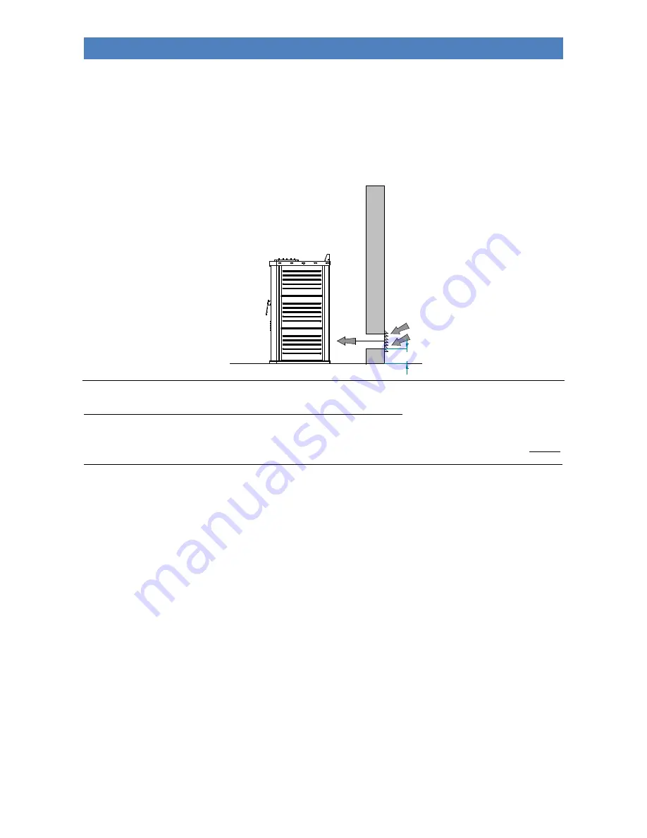
Do not connect the external air vent directly to the appliance through piping. If there are other heating or extraction 

devices inside the room, the air vents must guarantee a sufficient amount of air for properly operating all the devices.  

 
Only sealed appliances (e.g. C type gas appliances, according to the UNI 7129 Standard) or appliances that do not 

cause a lower pressure compared with the external environment can pre-exist or be installed in the place where the 

appliance is installed. 

Extractor fans can cause malfunctions to the appliance if used in the same room. 


Fig. A

20


The flue pipe and connection to the same 

The flue pipe is an essential element for the efficient operation of the appliance. The flue must have a minimum cross-

sectional area as that indicated in the technical specifications of the appliance (100 mm). Each product must be 

equipped with its own flue, without other adjoining elements (boilers, chimneys, stoves etc.). The flue dimensions are 

closely related to its height, which must be measured from the appliance flue gas outlet to the base of the stack. In order 
to guarantee adequate draught, the chimney stack flue outlet surface must be twice as big as the flue pipe cross-section. 

The discharge pipe for combustion products generated by the forced draught device, must comply with the following 

requirements: 

-


It must seal off the combustion gases, as well as being waterproof and suitably isolated and insulated in relation to 

the conditions of use (refer to UNI 9615); 

-


It must be made of suitable materials capable of withstanding normal mechanical stress, heat, and the effects of 

combustion gases and condensate, if any; 

-


It must go upwards after the vertical section, for the entire remaining part, with a minimum gradient of 5%; The sub-

horizontal section must not have a length greater than ¼ of the effective height H of the flue or chimney, and must 

not be longer than 2,000 mm

-


It must preferably have a round internal cross-section: square or rectangular cross-sections must have rounded 
corners with radius not inferior to 20 mm; 

-


It must have a constant, free and independent internal cross section; 

-


Rectangular cross-sections must have a maximum ratio of 1.5 between the sides; 

-


If the flue pipe is installed on the outside it is essential that it is insulated in order to avoid the flue gas cooling 

allowing condensation to form; 

-


Parts made from non-combustible materials (it is absolutely prohibited the use of aluminium flue pipe) - capable 

of withstanding combustion gases and potential condensation - must be used for mounting the flue gas pipes (for the 

section from the appliance to the flue inlet); 

-


It is forbidden to use fibre cement pipes to connect the appliance to the flue; 

-


Flue pipes must not pass through rooms in which the installation of combustion devices is prohibited; 

-


The flue pipes must be assembled in such a way as to guarantee adequate sealing of flue gases during low pressure 
operation of the appliance; 

-


The installation of horizontal sections is prohibited; 

-


It is prohibited to use counter sloping elements; 

-


The flue gas pipe must allow for the recovery of soot or be cleanable, and must have a constant cross-section; 

Summary of Contents for STAR 14

Page 1: ...ENGLISH STAR 14 Pellet boiler stove INSTALLATION USE AND MAINTENANCE USEFUL TIPS...

Page 2: ......

Page 3: ...e A1 Distance from combustible material 200 mm Fuel spillage risk Compliant Emission of combustion products Nominal power Reduced power CO at 13 of O2 0 010 CO at 13 of O2 0 037 Effective temperature...

Page 4: ...ONTROL OF ANY COUPLED BOILER 14 CONNECTION TO THE ROOM THERMOSTAT 15 HYDRAULIC CONNECTION 15 THE DISPLAY 16 THE MENU 18 INITIAL START UP 22 FILLING THE SYSTEM FOR THE FIRST TIME 22 PELLET LOADING AND...

Page 5: ...nce and its operation instructions for proper installation basic maintenance and control points which must be periodically performed furthermore it contains practical advice which helps to obtain maxi...

Page 6: ...ncinerator or for any use other than that for which it was designed Do not use fuels other than those recommended Do not use liquid fuels The appliance and its outer surfaces in particular become very...

Page 7: ...By laws and other regulations that affect the installation of the appliance The Building Regulations requirements can be met by adopting the relevant recommendations given in British Standards BS 8303...

Page 8: ...the heating system Expansion tank 8 l with pre load 1 bar Safety valve calibrated 2 5 bar REAR TECHNICAL COMPARTMENT Manual air vent valve with key and rubber pipe Return pipe connection of the heati...

Page 9: ...STAR 14 PELLET BOILER STOVE 6 EN Rev 2 1 Overall dimensions...

Page 10: ...STOVE 7 EN Rev 2 1 Connections data sheet Description of connections M System Delivery 3 4 F R System Return 3 4 M X Safety valve drain 1 2 F A Intake pipe 43 mm S Flue gas outlet 80 mm M E Electricit...

Page 11: ...037 Power consumption min max Watt 25 300 Nominal voltage V 220 Nominal frequency Hz 50 Expansion vessel litres preloading bar 8 1 Maximum operating recommended pressure bar 2 5 1 5 Flue pipe diamete...

Page 12: ...must be compliant with some international standards such as EN14961 2 DIN 51731 and O NORM M7135 which establish minimum values for quality checks on pellets To facilitate the right choice of the comb...

Page 13: ...d technical assistance centre where it is necessary to disconnect the device from the system will not be recognised under warranty as described in chapter Warranty Conditions External air intake Durin...

Page 14: ...onditions of use refer to UNI 9615 It must be made of suitable materials capable of withstanding normal mechanical stress heat and the effects of combustion gases and condensate if any It must go upwa...

Page 15: ...d 70 C IT IS MANDATORY TO HAVE AN INITIAL VERTICAL SECTION OF AT LEAST 1 5 MT IN ORDER TO GUARANTEE CORRECT FLUE GAS DISCHARGE Every direction change must be carried out with a T shaped fitting and in...

Page 16: ...TRICAL CONNECTION The electric connection must only be performed by qualified staff in compliance with all general and local safety standards Check that the power supply voltage and frequency correspo...

Page 17: ...standard boiler when the heating circulating pump of the pellet appliance starts up so as to avoid having two boilers operating simultaneously on the same system The coupled boiler is however always...

Page 18: ...pump of the system is forcedly switched on to ensure the disposal of excessive heat thus avoiding the reaching of high temperatures of the water in the boiler For this reason it is recommended that th...

Page 19: ...s any liability for damages caused due to incorrect assembly THE DISPLAY The appliance s operating mode is displayed on the console After turning on the menu it is possible to choose from many types o...

Page 20: ...display when setting or programming operating parameters Set 1 2 3 4 5 6 The INPUT area shows the entered programming values The MENU LEVEL area shows the current parameter menu level The DIALOGUE ar...

Page 21: ...ing power of the appliance Menu mode Moves you to the next menu item Programming mode Moves you to the next submenu item storing the changes made 6 Increase power 3 Working off Increases the working p...

Page 22: ...enable disable and set the programmable thermostat weekly program functions MENU LEVEL SELECTION MEANING POSSIBLE VALUES 02 03 01 CHRONO WEEKLY Enable disable the weekly programme ON OFF The weekly pr...

Page 23: ...TION MEANING POSSIBLE VALUES 02 04 01 CHRONO WEEK END Enable disable the weekend programme ON OFF 02 04 02 START 1 WEEK END Turn on time of the first programme Time OFF 02 04 03 STOP 1 WEEK END Turn o...

Page 24: ...rol the appliance with the boiler temperature only disable the room sensor on the Remote control Stove settings menu Enable room sensor OFF The room sensor is automatically disabled if no external Rem...

Page 25: ...ied or when it is filled for the first time Warning once the operation has been completed before switching on the appliance you should empty the accumulation of pellets deposited inside the brazier Me...

Page 26: ...arranty Ignition cycle Pressing button 4 ON OFF for a few seconds allows you to start the ignition cycle After a while the display shows START and the flue gas intake device and ignition resistance sw...

Page 27: ...rential set on Pr43 set as default at 5 C in other words if Temperature H2O SET H2O Pr43 The appliance automatically starts up again if the following condition occurs The temperature falls below the t...

Page 28: ...set temperature the appliance will perform the same procedure as with the opening of the room thermostat See Connection to the room thermostat Remote control The following table shows the function of...

Page 29: ...s not been done and if you have not filled the entire boiler body and system with water in order not to compromise its duration The noise level of the appliance is emphasised if the pellet container i...

Page 30: ...ure sensor AL 3 HOT TEMP Flue gas over temperature When flue gas temperature is higher than 260 C Before displaying the alarm or when flue gas maximum temperature is reached Pr14 the display shows HOT...

Page 31: ...ns use the personal protection devices specified in Directive 89 391 EEC The required cleaning frequency depends on the type and quality of the pellets used The schedule indicated below may therefore...

Page 32: ...prevent damaging the vacuum cleaner We do not recommend the use of normal vacuum cleaners Non routine cleaning The extraordinary cleaning of the appliance must be done at least every 15 days so as to...

Page 33: ...TOVE 30 EN Rev 2 1 Dismount the 4 flue diverters 2 on the right and 2 on the left placed on the combustion chamber sides figure 6 e 7 and scrape the internal walls with a spatula removing any deposit...

Page 34: ...e boiler body Then reassemble the 4 flue diverters its bottom and the ash box To ensure correct operation it is necessary to remove the sawdust deposited on the base of the tank Figure 10 at least onc...

Page 35: ...aranteeing correct operation optimal heat performance and durability of the device Therefore qualified staff should check the appliance at least once a year at the beginning of the season You must per...

Page 36: ...4 11 Automatic re ignition after blackout BLACKOUT IGNITION Seconds 0 60 30 Pr49 M 9 4 12 Pellet level sensor enable PELLET RESERVE On off On off Off Pr50 M 9 4 13 Pump start for over temperature saf...

Page 37: ...in output 1 working mode NOT USED AIR 1 SPEED Volt 65 225 65 Pr24 M 9 6 24 Exchanger 1 motor speed in output 2 working mode NOT USED AIR 2 SPEED Volt 65 225 65 Pr25 M 9 6 25 Exchanger 1 motor speed in...

Page 38: ...ALT MANUAL RESET THERMOSTAT FUSE 4A 5X20 CN12 CN10 PCB L023 CN14 CONNECTOR FOR BOOTLOADER CONNECTION WIRES 220 V FOR CONTROLLING COUPLED BOILER IF CONNECTED AUX BLUE RED P M FOR THE ELECTRICAL CONNEC...

Page 39: ...where it is not proved that their condition is due to a manufacturing defect rather than the effects of wear electric and electronic parts in which the malfunction can be traced to a non compliant el...

Page 40: ...Cod CS IST ST14 EN FP KLOVER Srl Via A Volta 8 37047 San Bonifacio VR P IVA 02324280235 www klover it...

Reviews: