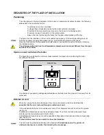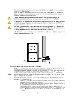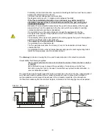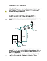
27
THE DISPLAY
The equipment's functioning state is displayed by the console. Many types of displays and the available
settings based on the selected menu can be made by accessing the menu.
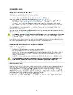
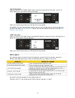
The following figure shows the display in equipment on or off conditions.
Set
!
1
2
3
4
5
6
Set
!
1
2
3
4
5
6
The following figure describes the meaning of the state signals on the display's left wall
(1st LED SERIES).
!
ROOM THERMOSTAT: the LED is on when room thermostat contact is open.
CHRONO-THERMOSTAT: the LED is on when at least one ignition and switch-off program is
active.
IGNITION RESISTANCE: the LED is on when ignition resistance is active.
SCREW FEED: the LED is on when the pellet load motor reducer switches on.
FLUE GAS EXTRACTOR: the LED is on when the flue gas intake device is active.
DHW FLOW SWITCH: the LED is on when DHW flow switch contact is closed (DHW is requested).
PUMP: the LED is on when system circulation pump is active.
ALARM: the LED is on when the boiler is in alarm state.
2nd LED
SERIES
1st LED
SERIES
17:19
- - - - 60°
C
OFF
DIALOGUE
WATER TEMPERATURE
CLOCK
ROOM TEMPERATURE (optional)
Summary of Contents for pellet boiler 24
Page 1: ...Pellet boiler PELLET BOILER 24 INSTALLATION USE AND MAINTENANCE USEFUL ADVICE User guide EN ...
Page 2: ......
Page 4: ...4 ...
Page 47: ...47 ...

