background image

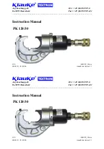
Instruction 

Manual 

PK 

120/30       page 

24 

_____________________________________________________________________________ 
 

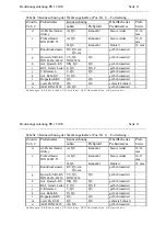
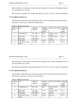
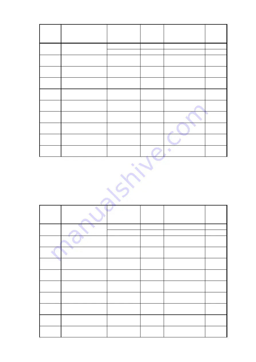
relation 
Tab. 2 

dies marking 

outside 

marking 
crimping 
profile 

surface of the dies  crimping

width 
[mm] 

Al, „QS“ 

code # 

blue zinc 

10-15  

e Compression 

joint 

DIN 48085 part 3 

ST, „QS“ 

code # 

black 

14  

Pre-rounding dies 

RU; QS, sm;  
        QS, sm 

- chrome 

plated, 

yellow 

g Terminals 

DIN 46234/46230 

CU, „QS“, 
DIN 46234 

QS chrome 

plated, 

yellow 

Insulated terminals 

ISQ, QS 

QS 

chrome plated, 
yellow 

Tub. CL for fine-str. 
conductors 

F, QS 

QS 

chrome plated, 
yellow 

C-clamps 

C, QS 

chrome plated, 
yellow 

Pre-insulated tub. CL 
and connectors 

IS, QS 

QS 

chrome plated, 
yellow 

l Double 

compression 

CL 

DP, QS 

QS 

chrome plated, 
yellow 

m Oval 

compression 

joints 

CU or AL, QS  code # 

chrome plated, 
yellow 

AEH DIN 46228 

AE, QS 

chrome plated, 
yellow 

A b b r e v i a t i o n s :   C L - t u b u l a r   c a b l e   l u g s ,   A E H - c a b l e   e n d - s l e e v e s ,   Q S - C r o s s - s e c t i o n  


Instruction 

Manual 

PK 

120/30       page 

24 

_____________________________________________________________________________ 


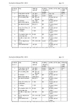
relation 
Tab. 2 

dies marking 

outside 

marking 
crimping 
profile 

surface of the dies  crimping

width 
[mm] 

Al, „QS“ 

code # 

blue zinc 

10-15  

e Compression 

joint 

DIN 48085 part 3 

ST, „QS“ 

code # 

black 

14  

Pre-rounding dies 

RU; QS, sm;  
        QS, sm 

- chrome 

plated, 

yellow 

g Terminals 

DIN 46234/46230 

CU, „QS“, 
DIN 46234 

QS chrome 

plated, 

yellow 

Insulated terminals 

ISQ, QS 

QS 

chrome plated, 
yellow 

Tub. CL for fine-str. 
conductors 

F, QS 

QS 

chrome plated, 
yellow 

C-clamps 

C, QS 

chrome plated, 
yellow 

Pre-insulated tub. CL 
and connectors 

IS, QS 

QS 

chrome plated, 
yellow 

l Double 

compression 

CL 

DP, QS 

QS 

chrome plated, 
yellow 

m Oval 

compression 

joints 

CU or AL, QS  code # 

chrome plated, 
yellow 

AEH DIN 46228 

AE, QS 

chrome plated, 
yellow 

A b b r e v i a t i o n s :   C L - t u b u l a r   c a b l e   l u g s ,   A E H - c a b l e   e n d - s l e e v e s ,   Q S - C r o s s - s e c t i o n  
Summary of Contents for PK 120/30

Page 1: ...edienungs und Wartungsanleitung Instruction Manual JCS HE 8352_D 8 00 Anzahl der Seiten 31 Bedienungs und Wartungsanleitung Instruction Manual JCS HE 8352_D 8 00 Anzahl der Seiten 31 PK 120 30 PK 120 30 ...

Page 2: ...m Kunden selber ausgetauscht werden dürfen 5 6 Transport 6 Verhalten bei Störungen 7 Technische Daten Bedienungsanleitung PK 120 30 Seite 2 ___________________________________________________________________________ Inhaltsangabe 1 Einleitung 2 Aufschriften 3 Gewährleistung 4 Beschreibung des hydraulischen Preßkopfes 4 1 Beschreibung der Komponenten 4 2 Beschreibung des Preßvorganges 5 Hinweise zu...

Page 3: ...iebsanleitung zugänglich machen und sich vergewissern daß der Bediener sie gelesen und verstanden hat Bedienungsanleitung PK 120 30 Seite 3 ___________________________________________________________________________ Bedienungsanleitung für das hydraulische Preßwerkzeug Typ PK 120 30 Seriennummer 1 Einleitung Vor Inbetriebnahme Ihres Preßwerkzeuges lesen Sie sich die Bedienungsanleitung sorgfältig ...

Page 4: ...hgemäßer Bedienung und unter Einhaltung der geforderten regelmäßigen Kontrollen 1 Jahr ab Lieferdatum Bedienungsanleitung PK 120 30 Seite 4 ___________________________________________________________________________ 2 Aufschriften An dem Preßkopf finden Sie jeweils einen Aufkleber mit Firmenlogo Firmennamen Typenangabe und dem zulässigen Betriebsüberdruck Die Seriennummer befindet sich auf dem Hyd...

Page 5: ... folgenden Komponenten Bild 1 Einsätze Preßkopf Kupplung Einsätze Pos Nr 1 Pos Nr 2 Pos Nr 3 Pos Nr 1 Bedienungsanleitung PK 120 30 Seite 5 ___________________________________________________________________________ 4 Beschreibung des hydraulischen Preßwerkzeuges 4 1 Beschreibung der Komponenten Das hydraulische Preßwerkzeug bestehen aus folgenden Komponenten Bild 1 Einsätze Preßkopf Kupplung Eins...

Page 6: ...se zur Verpressung von Verbindungsmaterialien entnehmen Sie bitte unserem Montagehinweisen im Katalog Bedienungsanleitung PK 120 30 Seite 6 ___________________________________________________________________________ 4 2 Beschreibung des Preßvorganges Beim Preßvorgang werden die Werkzeugeinsätze gegeneinander gefahren Der auf das Kabel aufgeschobene Kabelschuh Verbinder befindet sich in der festste...

Page 7: ...n die Ausgangs position zurückgefahren und das Verbindungsmaterial aus dem Preßkopf Pos Nr 2 entfernt Bedienungsanleitung PK 120 30 Seite 7 ___________________________________________________________________________ 5 Hinweise zum bestimmungsgemäßen Gebrauch In Verbindung mit einem 2 m Hochdruckschlauch ist das Arbeiten im Kabelgraben nicht möglich Für diese Anwendung wird mindestens ein 3 m Schla...

Page 8: ..._____________________________________________________________________________________________________ Bedienungsanleitung PK 120 30 Seite 8 ___________________________________________________________________________ 5 2 Erläuterung des Anwendungsbereiches Unser hydraulisches Preßkopf vom Typ PK 120 30 verfügt über eine große Anzahl verschiedener Werkzeugeinsätze Pos Nr 1 zum Verpressen von Cu und ...

Page 9: ...bindungsmaterialien verpreßt werden müssen ist eine Rücksprache mit dem Werk zwingend erforderlich Bedienungsanleitung PK 120 30 Seite 9 _____________________________________________________________________________ Preßbereich Verbindungsmaterial _____________________________________________________________________________________________________________ g 16 150 mm Quetschkabelschuhe DIN 46234 St...

Page 10: ... CU QS DIN 46235 Kennzahl gelb chromatiert 10 17 mm c Aluminium AL QS Kennzahl blau verzinkt 12 17 mm Bedienungsanleitung PK 120 30 Seite 10 ___________________________________________________________________________ Achtung Desweiteren dürfen keine unter Spannung stehenden Teile verpreßt werden Vor Arbeitsbeginn ist ein spannungsfreier Zustand der zu verpressenden Verbindung sicherzustellen Das G...

Page 11: ... 46228 AE QS gelb chromatiert Abküzungen KS Kabelschuhe VB Verbinder AEH Aderendhülsen QS Querschnitt Bedienungsanleitung PK 120 30 Seite 11 ___________________________________________________________________________ Tabelle 3 Kennzeichnung der Werkzeugeinsätze Pos Nr 1 Fortsetzung Kennzeichnung Zuordn Tab 2 Preßeinsätze außen Preßprofil Oberfläche des Preßeinsatzes Preß breite d Al Preßverbinder ...

Page 12: ...g ist weitgehend wartungsfrei Der Preßkopf Pos Nr 2 ist nach möglichen Beschädigungen zu untersuchen Bedienungsanleitung PK 12030 Seite 12 ___________________________________________________________________________ Mit den in Tabelle 3 Abs a aufgeführten Einsätzen dürfen ausschließlich handelsübliche Klauke Rohrkabelschuhe und Verbinder verarbeitet werden Eine Verpressung von handelsüblichen Kabel...

Page 13: ...us muß das jeweilige Bauteil oder ggf das gesamte Aggregat zur Reparatur ins Werk eingeschickt werden Bedienungsanleitung PK 120 30 Seite 13 ___________________________________________________________________________ 5 5 Hinweis welche Ersatz Teile vom Kunden selber ausgetauscht werden dürfen Innerhalb des Gewährleistungszeitraums darf vom Kunden nur die Werkzeugeinsätze gewechselt werden 5 6 Tran...

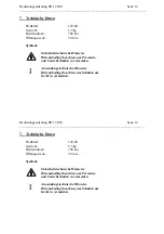
Page 14: ...u vermeiden Anwendungstechnische Hinweise Bitte unbedingt beachten um Schäden am Gerät zu vermeiden Bedienungsanleitung PK 120 30 Seite 14 ___________________________________________________________________________ 7 Technische Daten Preßkraft 120 kN Gewicht 5 5 kg Betriebsdruck 700 bar Öffnungsweite 30 mm Symbole Sicherheitstechnische Hinweise Bitte unbedingt beachten um Personen und Umweltschäde...

Page 15: ...__________________ Instruction Manual JCS HE8352_D doc HE 8352_D 8 00 Anzahl der Seiten 31 Auf dem Knapp 46 Tel 49 0 2191 907 0 D 42855 Remscheid Fax 49 0 2191 907 141 ____________________________________________________________________________ Instruction Manual JCS HE8352_D doc HE 8352_D 8 00 Anzahl der Seiten 31 PK 120 30 PK 120 30 ...

Page 16: ...eference as to which spare parts can be exchanged by the customer 6 Troubleshooting 7 Technical data Instruction Manual PK 120 30 page 16 _____________________________________________________________________________ Index 1 Introduction 2 Labels 3 Warranty 4 Description of the hydraulic crimping tool 4 1 Description of the components 4 2 Description of the crimping processes 5 Remarks with respect...

Page 17: ...fication name of the manufacturer and or the company logo The Serial No is on the hydraulic cylinder Instruction Manual PK 120 30 page 17 _____________________________________________________________________________ Instruction Manual for the hydraulic crimping tool Type PK 120 30 Serial No 1 Introduction Before starting to use the tool please read the instruction manual carefully Use this tool ex...

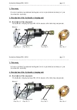
Page 18: ... following components Picture 1 Dies Crimping head Coupling Dies Pos No 2 Pos No 1 Pos No 3 Pos No 2 Instruction Manual PK 120 30 page 18 _____________________________________________________________________________ 3 Warranty If correct operation is guaranteed and regular service is provided our warranty is 1 year from the time of delivery 4 Description of the hydraulic crimping unit 4 1 Descript...

Page 19: ...t possible to work in a cable trench For this application at least a 3m high pressure hose is needed Instruction Manual PK 120 30 page 19 _____________________________________________________________________________ 4 2 Description of the crimping procedure A crimping process is characterized by the closing motion of the dies Pos No 2 The cable lug or connector will be positioned in the stationary...

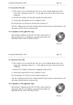
Page 20: ... No 2 available to crimp primarily copper and aluminium but also other connecting material Picture 2 Instruction Manual PK 120 30 page 20 _____________________________________________________________________________ 5 1 Operation of the unit 1 First you have to select the right dies Pos No 2 for the intended application Then connect the crimping head Pos No 1 to the high pressure hose and roll out...

Page 21: ...________________________________________ i 16 150 mm Tubular cable lugs for fine stranded conductors Instruction Manual PK 120 30 page 21 _____________________________________________________________________________ Table 2 Crimping range Connecting material _____________________________________________________________________________________________________________ a 16 300 mm Tubular cable lugs ...

Page 22: ...s have to be crimped please contact the manufacturer Attention Do not use on or near live circuits Instruction Manual PK 120 30 page 22 _____________________________________________________________________________ Crimping range Connecting material continuing table 2 _____________________________________________________________________________________________________________ j 10 70 mm C clamps __...

Page 23: ...w 10 17 c Aluminium AL QS code blue zinc 12 17 d Compression joint Aldrey Al QS code blue zinc 12 14 Instruction Manual PK 120 30 page 23 _____________________________________________________________________________ Before starting to crimp please make sure that all parts involved in the crimping process are not connected to live circuits The unit can be operated in a temperature range from 20 C t...

Page 24: ...E QS chrome plated yellow Abbreviations CL tubular cable lugs AEH cable end sleeves QS Cross section Instruction Manual PK 120 30 page 24 _____________________________________________________________________________ relation Tab 2 dies marking outside marking crimping profile surface of the dies crimping width mm Al QS code blue zinc 10 15 e Compression joint DIN 48085 part 3 ST QS code black 14 f...

Page 25: ... the determined use of the tool only the dies Pos No 2 are permitted to be changed by the customer Instruction Manual PK 120 30 page 25 _____________________________________________________________________________ With those dies mentioned in Table 3a only Klauke cable lugs and connectors Standard type are supposed to be crimped Crimping of commercial cable lugs and connectors of other suppliers w...

Page 26: ...onmental damages Operational warnings Please do not disregard them to avoid damaging the pump unit Instruction Manual PK 120 30 page 26 _____________________________________________________________________________ Do not attempt to repair the tool yourself and do not remove any parts such as screws and other components 6 Troubleshooting The tool loses oil Return the tool to the manufacturer Do not...

Page 27: ...orgaccio di Soltara PU Italy Tel 39 0721 892168 Fax 39 0721 879602 E MAIL produzione fb avvolgitori it Service Seite page 27 __________________________________________________________________________________________________________________ PORTUGAL Palissy Galvani Electricidade Lda Mr Ana Pereira Rua Serpa Pinto 15 A P 1200 Lisboa Portugal Tel 351 21 3223400 Fax 351 21 3223410 DEUTSCHLAND Klauke R...

Page 28: ... M Pujmanove 1220 31 14000 Praha 4 Prankrac Tschechische Republik Tel 42 2 61213220 Fax 42 2 61213218 Service Seite page 28 __________________________________________________________________________________________________________________ SLOWENIEN Isaria d o o Mrs Zorz Proizvdnja in trgovina Cece 2a 1420 Trovlje Slowenien Tel 386 356 31800 Fax 386 356 3180 RUSSLAND Unit Mark Pro Mr Alexander Naic...

Page 29: ... Zhang Yulian No 7 234 Changning Road 200042 Shanghai China ZIP Tel 86 21 62254404 Fax 86 21 62254404 Service Seite page 29 __________________________________________________________________________________________________________________ ISRAEL Shay A U Ltd Mr Shay Ind Zone Kiriat Arieh Embar Street 23 25 P O BOX 10049 49222 Petach Tikva Israel Tel 972 3 9233601 Fax 972 3 9234601 E MAIL a_u shay ...

Page 30: ...son Kärsämäentie 23 20360 Turku Finnland Tel 00358 2 4100200 Fax 00358 2 4100229 E Mail info elteo fi Service Seite page 30 __________________________________________________________________________________________________________________ Geplante planned Service Center in 2004 IRLAND Mangan Wholesale Ltd Chapelizod 39 40 Main Street Dublin 20 Irland Tel 00353 1 6267611 Fax 00353 1 6267613 E Mail ...

Page 31: ...g von Eigenschaften Die Sicherheitshinweise der mitgelieferten Produktdokumentation sind zu beachten EG Herstellererklärung nach Art 4 Abs 2 der EG Richtlinie 98 37 EG Dokument Nr Monat Jahr 001PK12030 08 00 Hersteller Firma Gustav Klauke GmbH Anschrift Auf dem Knapp 46 D 42855 Remscheid Produktbezeichnung hydraulischer Preßkopf Typ PK 120 30 Die Inbetriebnahme ist so lange untersagt bis die Konfo...

Reviews: