


-16-
-17-
to the «+» welding cable socket, and the
cable with the “Mass” clamp to the «-»
welding cable socket
6.
Turn the machine mode switch
(see Fig. p.11, item 6) to MMA welding
position.
7.
Connect the “Mass” terminal to the
workpiece or welding table.
8.
Insert the electrode into the elec-
trode holder.
9.
After you make sure that the elec-
trode holder and the electrode do not
touch the parts connected to the neg-
ative terminal, connect the machine to
the mains power supply and turn it on.
10.
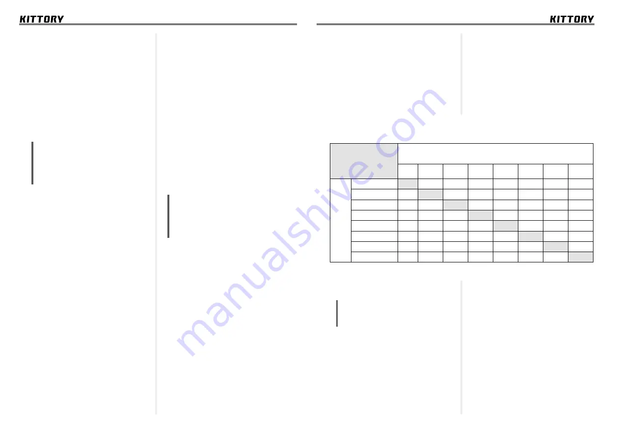
Set the required welding current
Electrode diameter, mm
Metal thickness, mm
0,5
1-2
3
4-5
6-8
9-12
13-15
16
W
elding current, A
10-20
1
30-45
1,5-2
65-100
2-3
100-160
3-4
120-200
4-5
150-200
4-5
160-250
5
200-350
6-8
Table of selecting electrode
diameter depending on the metal
thickness and welding current
Maintanence
ATTENTION!
Disconnect power
source before performing any
maintanence work.
Long service life and efficient oper-
ation of the welding machine directly
depend on its technical condition.
Regularly monitor the machine con-
dition. If damage occurs, repair the
machine immediately. Do not oper-
ate the machine in overload condi-
tion. Strictly observe the switching
frequency. Avoid impacts or other
mechanical damage of the case and the
machine operational panel. Do not keep
the machine in moist or damp areas.
Inverter welding machine is a reli-
able equipment. Observance of simple
safety rules and timely maintenance can
significantly increase the operational
lifespan.
Keep the welding machine in good
condition.
Carry out preventative maintanance
and timely repairs of the machine.
(see Fig. p.11, item 1) and start work.
Maintanence
arc damage and the welding process
shutdown.
6.
Setting the wire feed speed: The
wire feed speed control (see Fig. 11,
item 4) controls the speed of the wire
that is being fed through the MIG torch.
The wire feed speed must be precisely
set at the level when the wire fully
melts. When setting the wire feed speed,
check the wire type, diameter, volt-
age and positioning of the seam. The
welding current changes if the wire feed
speed adjusted.
NOTE:
The wire will move faster
if you do not strike the welding
arc. On the contrary the wire feed
speed will be lower if you strike
the welding arc.
7.
Connect the earth terminal to the
metal part identical to the one you will
be welding on. The metal part should be
the same thickness or slightly thicker
than the workpiece. Clean the workpiece
before you start welding.
8.
Adjust the required welding
voltage.
9.
Bring the torch close to the work-
piece, make sure to position the torch
following the recommendations of this
manual.
10.
With your free hand, turn the wire
speed control knob to the maximum and
keep holding the knob.
11.
Draw the protective mask and
press the MIG torch trigger to strike the
arc, start moving the torch forehand
or backhand, simultaniously turn-
ing the wire feed speed control knob
counterclockwise.
12.
While adjusting the wire feed
speed, the sound produced by the
welding arc will change from the sharp
buzzing sound to a slight sizzling bacon
sound. If you reduce wire feed speed
too much, you will hear a sharp sound
and bangs. The wire feed speed is
correct when you hear a steady sizzling
sound. By slightly changing the wire
feed speed, you can control the tem-
perature and fill rate of the weld when
the arc voltage settings are set and not
changed. Repeat the above procedure if
you have adjusted the voltage, diameter
or type of the welding wire.
13.
After welding operations are
completed, set all the controls to the
minimum position, close the valve on
the cylinder and unplug the machine.
MMA operation
ATTENTION!
Follow the safety
rules! Start work only in appro-
priate tightly woven clothes and
closed boots. Welding gloves and
a mask must be worn at any time!
If the welding machine was used
for welding in the MIG mode, take the
following steps to prepare it for opera-
tion in the MMA welding mode (covered
electrode welding):
1.
Unplug the welding machine.
2.
Turn the gas cylinder valve off and
disconnect the hose from the socket on
the back of the welding machine.
3.
Disconnect the MIG torch. Loose
the feeder deflector roll and coil the wire
onto the spool.
4.
If the polarity of the negative termi-
nal has been changed to «+», restore it.
(See step 4 on page 13 of this manual).
5.
Connect the welding cables to the
machine: connect the electrode holder
MMA operation


