


-14-
-15-
MIG operation
6.4. Adjust the pressure roll force
(see Fig. 13, tem 3) so that it is not
clamped too tightly, and the wire does
not slip. Excessive clamping will lead to
premature wear of the pressure roll, while
slippage will complicate the welding
process.
6.5. Remove the MIG nozzle and a
conductive head from the torch, press
the torch trigger, pull the wire until it
emerges from the torch port.
6.6. Connect the conductive head
that exactly matches the wire diameter
to the torch and place the nozzle back
to its place.
6.7. Adjust the length by clipping off
the end of the wire with insulated cutters.
Repeat each time before starting work.
MIG operation
WARNING!
Never operate the
maching in wet weather or in a
humid room.
Never use cutting tools (drills,
grinders, electric saws, etc.) next
to the machine. Metal dust may
enter the machine and it will lead
to its damage.
Never carry out welding work if wire
or main supply cables are damaged.
Before switching on, keep the
machine for at least two hours at
a positive ambient temperature to
prevent condensation.
1.
Turn on the power switch (see Fig.
p. 11, item 12), the power indicator light
will turn on (see Fig. p.11, item 2).
2.
Select the MIG mode with the machine
mode switch (see Fig. p.11, item.6).
3.
Set the desired value with the weld-
ing current selector (see Fig. p.11, item 5).
The welding current selector controls
the temperature of the welding arc.
4.
Positioning of the MIG welding
torch: The best position of the welding
torch is the position convenient to com-
fortably hold it. In the process of using
your welding machine, try to keep the
torch in various positions until you find
the most convenient for you.
There are two major torch angles
which must be taken into account when
carring out welding works.
Angle A
may vary, but in most cases it
should be 60°. This is the angle at which
the torch handle is parallel to the weld-
ing seam. When the angle is greater,
the fill rate is higher. When the angle is
smaller, the fill rate is lower.
Angle B
can be applied in two cases:
to better see the arc for greater control
of the pool fill rate and for arc force
control.
5.
The distance between the con-
tact head of the welding torch and the
surface to be welded must not change
and should not exceed 6mm. A greater
distance will result in the welding
MIG installation
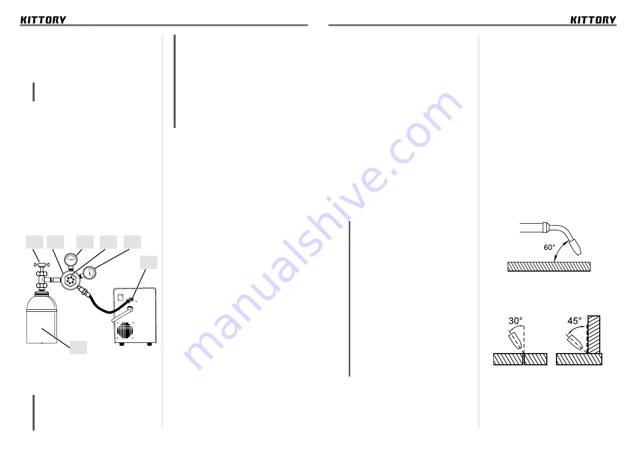
5.1. Connecting gas cylinder: Install
the gas cylinder on the prepared sur-
face. If necessary, fix it to avoid tipping
over.
ATTENTION!
Observe safety rules
when working with a gas cylinder!
5.2. Attach the gas regulator to the
cylinder valve.
5.3. Attach the gas hose of the gas
cylinder regulator outlet to the gas cylin-
der connector (see Fig. p. 11, item 11).
Gas cylinder connection diagram:
1 –Cylinder valve;
2 – Regulator;
3 – Cylinder pressure gauge;
4 –Pressure control valve;
5 – Gas flow meter gauge;
6 –Gas cylinder connector;
7 –Gas cylinder.
5.4. Set the required gas flow by turn-
ing the regulator knob.
Note:
The wire diameter, welding
current and welding speed affect gas
consumption. The average gas
consumption for welding construc-
tional steels with a welding wire diam-
eter of 0.8 and 1.0mm with welding
current of 60-160 is 8-9 l/min.
Gas consumption for non-ferrous
metals is usually 1.5-2 times higher.
When working in windy conditions
outside or inside in a draught,
protect the welding area from
blowing-out of the shielding gas.
5.5. Connect the device to the power
supply and switch on the automatic
switch on the back panel (see Fig. p. 11,
item 12).
5.6. Press the torch trigger and make
sure that the gas flows through the
gas valve into the torch. The gas valve
is located on the back of the welding
machine panel and is activated by press-
ing the trigger on the MIG torch. When
gas flows, listen for a hissing sound.
6.
Electrode wire. The type and thick-
ness of the wire is selected depending on
the chemical composition of the material
to be welded and its thickness. Welding
wire diameter is selected in accordance
with the required welding current level.
Most often, a wire with a diameter of
0.8 mm is sufficient for welding metal
with a thickness of 1 to 4 mm. The most
common wire brand for welding car-
bon-constructional steels is ER70S-6.
6.1. Install the wire weld coil in the
feeder (see Fig. p. 13, item 1).
6.2. Make sure that the deflector roll
is installed in a way that the groove
matches the wire diameter. If needed,
turn the roll over by untwisting the lock-
ing screw (see Fig. p. 13, item 5).
6.3. Insert the wire into the feeder
and press it with the pressure roll (see
Fig. p. 13, item 3).
7
6
1
2
3
4
5


