13
Verify Anti-Tip Bracket Is Installed
and Engaged
On Ranges Equipped with a Storage Drawer:
1.
Remove the storage drawer. See “Storage Drawer” section.
2.
Use a flashlight to look underneath the bottom of the range.
3.
Visually check that the rear range foot is inserted into the slot
of the anti-tip bracket.
On Ranges Equipped with a Warming Drawer or Premium
Storage Drawer:
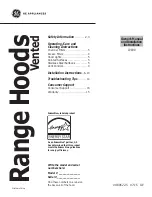
1.
Place the outside of your foot against the bottom front of the
warming drawer or premium storage drawer, and grasp the
lower right-hand or left-hand side of the control panel as
shown.
NOTE:
If your countertop is mounted with a backsplash, it
may be necessary to grasp the range higher than is shown in
the illustration.
2.
Slowly attempt to tilt the range forward.
If you encounter immediate resistance, the range foot is
engaged in the anti-tip bracket.
3.
If the rear of the range lifts more than ½" (1.3 cm) off the floor
without resistance, stop tilting the range and lower it gently
back to the floor. The range foot is not engaged in the anti-tip
bracket.
IMPORTANT:
If there is a snapping or popping sound when lifting
the range, the range may not be fully engaged in the bracket.
Check to see if there are obstructions keeping the range from
sliding to the wall or keeping the range foot from sliding into the
bracket. Verify that the bracket is held securely in place by the
mounting screws.
4.
Slide the range forward, and verify that the anti-tip bracket is
securely attached to the floor or wall.
5.
Slide range back so the rear range foot is inserted into the
slot of the anti-tip bracket.
IMPORTANT:
If the back of the range is more than 2" (5.1 cm)
from the mounting wall, the rear range foot may not engage the
bracket. Slide the range forward and determine if there is an
obstruction between the range and the mounting wall. If you
need assistance or service, refer to the “Assistance or Service”
section of the Use and Care Guide, or the cover or “Warranty”
section of the User Instructions, for contact information.
6.
Repeat steps 1 and 2 to ensure that the range foot is
engaged in the anti-tip bracket.
If the rear of the range lifts more than ½" (1.3 cm) off the floor
without resistance, the anti-tip bracket may not be installed
correctly. Do not operate the range without anti-tip bracket
installed and engaged. Please reference the “Assistance or
Service” section of the Use and Care Guide, or the cover or
“Warranty” section of the User Instructions, to contact
service.
Level Range
Determine if you have AquaLift
®†
Technology or Steam Clean by
referring to the “Range Care” section of the User Instructions.
For Ranges with AquaLift
®
Technology or Steam Clean:
1.
Place level on the oven bottom as indicated in one of the two
figures below, depending on the size of the level. Check with
the level: side to side and front to back.
2.
If range is not level, pull range forward until rear leveling leg is
removed from the anti-tip bracket.
3.
Follow the directions in Style 1 or Style 2, depending on the
style of drawer supplied with the range.
For Ranges without AquaLift
®
Technology or Steam Clean:
1.
Place a standard flat rack in oven.
2.
Place level on the rack and check levelness of the range, first
side to side; then front to back.
3.
If range is not level, pull range forward until rear leveling leg is
removed from the anti-tip bracket.
4.
Follow the directions in Style 1 or Style 2, depending on the
style of drawer supplied with the range.
Style 1: Ranges Equipped with a Storage Drawer:
Use
a ¼" drive ratchet, wrench or pliers to adjust leveling legs
up or down until the range is level. Push range back into
position. Check that rear leveling leg is engaged in the anti-tip
bracket.
†® AQUALIFT is a registered trademark of Whirlpool, U.S.A.