background image

Measuring Range/Introduction of Force 


9327C_002-477e-05.10  

Page 

15 

5.2


6-Component Force Measurement Using a Dynamometer 

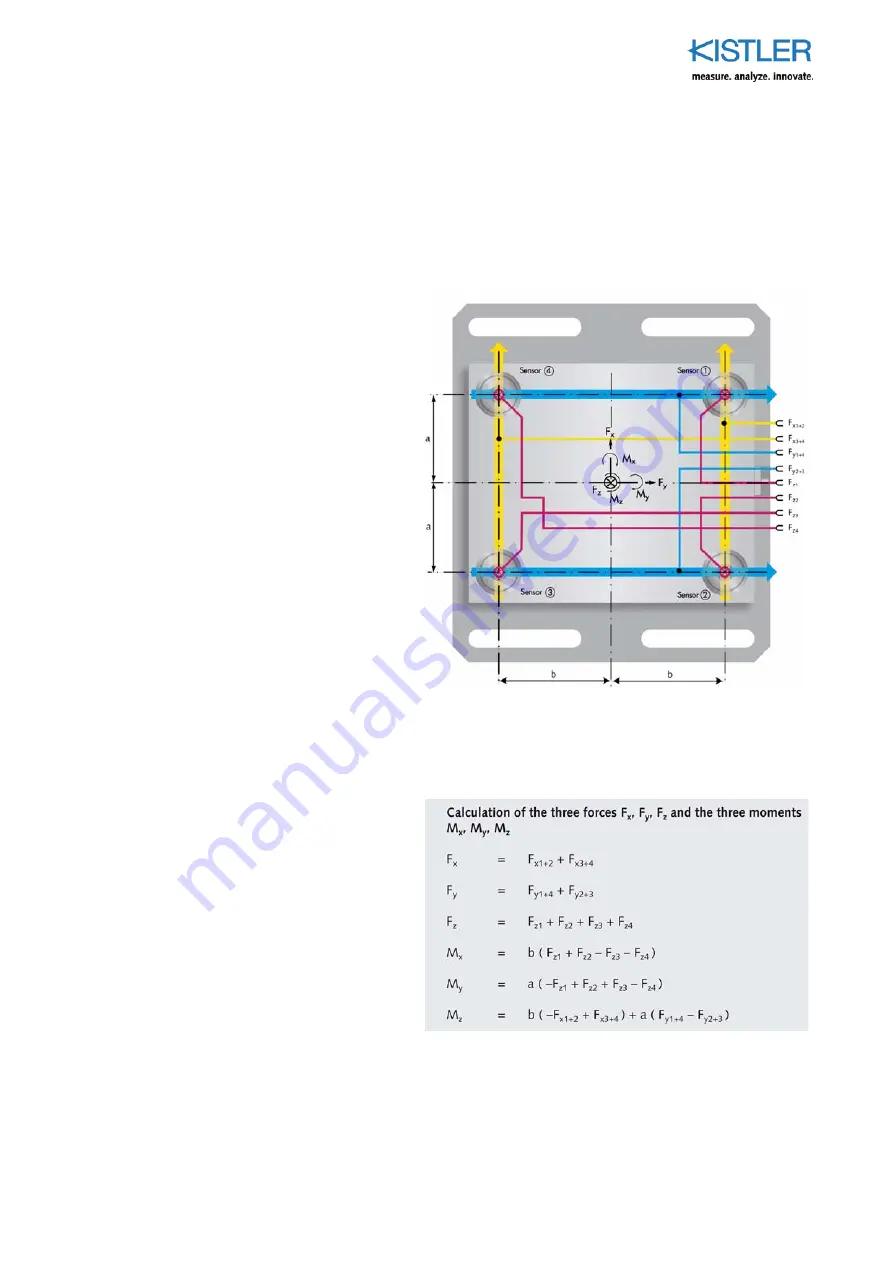
For a 6-component force measurement, the output signals 
of the four 3-component force sensors are interconnected 
as in Fig. 8. 

Fig. 8:  Interconnection of the twelve sensor outputs fort 

he 6-component force measurement 


The Three Forces and Three Moments can be Calculated 
from the Eight Measuring Signals as Follows


Fig. 9:  Algorithm for calculating the six force components 

Summary of Contents for 9327C

Page 1: ...Instruction Manual 3 Component Force Link Type 9327C 9327C_002 477e 05 10...

Page 2: ...Instruction Manual 3 Component Force Link Type 9327C 9327C_002 477e 05 10 Fz Fx Fy...

Page 3: ...o change without notice Kistler reserves the right to change or improve its products and make changes in the content without obliga tion to notify any person or organization of such changes or improve...

Page 4: ...sing a Dynamometer 13 5 2 6 Component Force Measurement Using a Dynamometer 15 5 3 3 Component Force Measurement Using a Single Force Sensor 16 5 4 Measuring System with 3 Component Force Link 21 5 5...

Page 5: ...Content 9327C_002 477e 05 10 Page 3 10 Annex 38 10 1 Glossary 38 10 2 Measurement Uncertainty 41 10 3 Linearity 42 10 4 Frequency Range 44 10 5 Influence of Temperature 45 10 6 Index 47 Total pages 47...

Page 6: ...tion and acoustic emission Strain gage sensor systems for measuring force and tor que Piezoresistive pressure sensors and transmitters Signal conditioners indicators and calibrators Electronic control...

Page 7: ...erating instructions The sensor must be installed operated and maintained only by persons who are familiar with the instrument and are adequately qualified for the work concerned If it is accepted tha...

Page 8: ...than 1013 In order to preserve this value all plug and socket connections must be kept absolutely clean and dry The insulation resistance can be meas ured with the insulation tester Type 5493 Protect...

Page 9: ...access to the information you require Please keep these instructions in a safe place where they are always to hand If you lose these instructions please contact your Kistler customer service organiza...

Page 10: ...ree orthogonal compo nents of any force acting on the sensor Fx Fy and Fz 3 component force links measure Cutting forces during machining Impact forces in crash tests Recoil forces of rocket engines V...

Page 11: ...on of the Instrument 9327C_002 477e 05 10 Page 9 Inertia Force Measurement Fig 2 Force limited vibration test Product Testing Fig 3 Elastomer test stand Reaction Force Measurement Fig 4 Rocket motor s...

Page 12: ...plates of which one is sensitive to pressure in the z direction and the two others to shear forces in the x and y directions Mea surement takes place practically without displacement The force introdu...

Page 13: ...component The latter has to be fixed firmly to the force link top plate The force link can be used as a single measuring ele ment or several of them with a common top plate force plate 4 2 Mounting of...

Page 14: ...e 12 9327C_002 477e 05 10 Mounting the top plate with 4 each M6 screws through the top plate Recommended Tightening Torques for Fixing Screws Thread Property Class ISO898 1 Tightening Torques MA N m M...

Page 15: ...g nals each of Fx Fy and Fz of the four sensors are summed However the sum of the four sensors always shows the correct value irrespective of the force application point A 3 component dynamometer meas...

Page 16: ...3 Component Force Link Type 9327C Page 14 9327C_002 477e 05 10 Fig 6 Force plate with solid top plate Fig 7 Force plate with top plate of any shape...

Page 17: ...measurement the output signals of the four 3 component force sensors are interconnected as in Fig 8 Fig 8 Interconnection of the twelve sensor outputs fort he 6 component force measurement The Three...

Page 18: ...an individual preloaded 3 component force sensor can only be utilized when the line of action of the resulting force vector runs through the center of the sensor i e the origin of the coordinate syste...

Page 19: ...point and the three compo nents of the resulting force are known the active moments can be calculated as follows Mx Fz ay Fy az My Fx az Fz ax Mz Fy ax Fx ay When calculating the moments it is essent...

Page 20: ...Preload force Fv 20 kN Coefficient of friction H 0 2 Force application point see Fig 10 Coordinates ax 4 mm ay 3 mm az 25 mm Process forces Fx 215 N Fy 130 N Fz 2 160 N Moments Mx Fz ay Fy az 9 7 N m...

Page 21: ...Measuring Range Introduction of Force 9327C_002 477e 05 10 Page 19 Fig 11 Nomogram to determine the max possible moment load Example...

Page 22: ...9327C_002 477e 05 10 Result max possible bending moment Mb My 2 Mx 18 N m max possible moment Mz 20 N m The sensor load is within the specifications The bending moment load is approximately 94 4 the m...

Page 23: ...3 Component Force Link 5 5 Measuring System with four 3 Component Force Links Dynamometer 1 see data sheet cables for multi component force sensors dynamometers and force plates 1687B_000 545 2 see d...

Page 24: ...all Force Changes The piezoelectric method of measurement allows very accurate measurement of small force changes when there is large preload present at the same time When for exam ple fluctuations Fz...

Page 25: ...1 N V for Fz f Set the amplifier to Short Time Constant g Switch the amplifier to Operate The Fz variations can now be measured with great accuracy since the dy namic response threshold is around 0 02...

Page 26: ...a drift up to 10 mN s can occur Depending on the measuring range therefore measure ments from a few minutes up to several hours are possible The illustration shows the example of a frequency curve in...

Page 27: ...ntroduction parts the higher is the resonant frequency and the wider is the usable fre quency range At the same time the mass mounted on the force link must be kept low Most piezoelectric force sensor...

Page 28: ...sis of sensor Repeatability of sensor Error of charge amplifier Average Linearity of charge amplifier The error can be improved if calibration is done in a partial range Electrical Drift The piezoelec...

Page 29: ...force link by tests Temperature Gradient Error The temporarily occurring maximum signal output of a sensor exposed to a temperature change is defined as Temperature gradient error The temperature gra...

Page 30: ...he error of the amplifier depends on the Type and the range capacitor It can vary between 0 5 FSO 2 FSO for lab Type charge amplifiers and 1 FSO 5 FSO for industrial charge amplifiers To improve the e...

Page 31: ...t the output signal stays between 5 10 V For normal force measurement set low pass filter to 1 3 of the resonance frequency Set charge amplifier to operating mode immediately before force measurement...

Page 32: ...e calibrations can even be done by our subsidiaries either by identical or by similar procedures Kistler keeps complete records available to our customers and allowing the calibration and repair recor...

Page 33: ...sor are machined parallel and flat within very close tolerances These surfaces should not be levelled with a whetstone Clean plug connectors of the sensor or connecting cable regularly with a cleaning...

Page 34: ...nsulation tester Type 5493 Clean plug connec tions During the measurement the charge amplifier goes into overload The force to be measured is too high for the measuring range selected Select a higher...

Page 35: ...Force application point 8 mm below the surface of the cover plate Fx Fy kN 0 1 0 0 1 Calibrated Range Force application point centric Fz kN 0 8 0 0 8 Permissible moment load Mz 0 Fz 0 Mx My N m 22 22...

Page 36: ...3 Component Force Link Type 9327C Page 34 9327C_002 477e 05 10 9 2 Dimensions 3 Component Force Link Type 9327C Fig 15 Dimensions 3 component force link Type 9327C...

Page 37: ...ories The following accessories can be obtained for sensor Type 9327C Fig 16 Connecting cable Type 1698AA see data sheet 16xx_000 545 Fig 17 Connecting cable Type 1698AB see data sheet 16xx_000 545 Fi...

Page 38: ...the dynamometer A maximum of eight measuring signals is available at the output socket similar to the Kistler standard dynamome ters Connection to the charge amplifier is made with a 3 core cable for...

Page 39: ...f summing box Type 5417 Fig 22 Cleaning and insulation spray 250 ml Type 1003 Fig 23 Insulation tester Type 5493 Ordering Code Type 3 Component Force Link 9327C 42x42x42 mm 8 8 kN Input Fx1 Fy1 Fz1 Fx...

Page 40: ...ts of the factory calibration Charge amplifier Part of a measuring chain which converts the charge signal from the sensor into a proportional voltage signal Charge signal Output signal in picocoulomb...

Page 41: ...tic which is measured e g force torque etc Measuring chain Interconnection of several individual components to meet measuring requirements Measuring chains usually consist of sensors and amplifiers in...

Page 42: ...tem which produces a definite change in the output signal as a function of the change of the measurand acting on it Temperature influence see Annex 10 5 Threshold Smallest change in the measurand whic...

Page 43: ...tion of the sensor and environmental influ ences For the highest accuracy requirements we recom mend calibration of measuring ranges specific to the appli cation Measurement uncertainty of charge ampl...

Page 44: ...ain unavoid able deviations occur due to the mechanical construction of the sensor Linearity represents the maximum deviation be tween ideal and actual output signal characteristics in rela tion to th...

Page 45: ...res 0 Linearity a resmax resmin Fig 24 Best straight line linearity and hysteresis Hysteresis Quartz itself has a scarcely measurable hysteresis How ever the mechanical construction of the sensor can...

Page 46: ...sing resonance rise Key f Measuring frequency fn Natural frequency A A0 Amplitude ratio The following approximate values apply to the amplitude error or achievable accuracy as a function of frequency...

Page 47: ...s then con tinuously varied until its natural frequency coincides with that of the actual sensor Technical data An equivalent body defined in this way is usually a good approximation of the sensor The...

Page 48: ...perature con stant during the actual measuring time Fig 26 Example of a temperature error of the output signal zero for a temperature rise from 150 C to 200 C immersion bath Temperature coefficient of...

Page 49: ...force measurement 9 Insulation resistance 6 40 Isolationspr fger t 37 L Linearity 40 M Measurand 40 Measuring chain 40 Measuring range 40 Measuring uncertainty 42 Moments 18 N Natural frequency 40 45...

Reviews: