background image

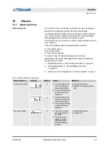
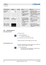
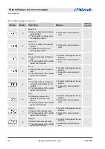
Display

Buzzer

Description

Measure

Unit key

required

3

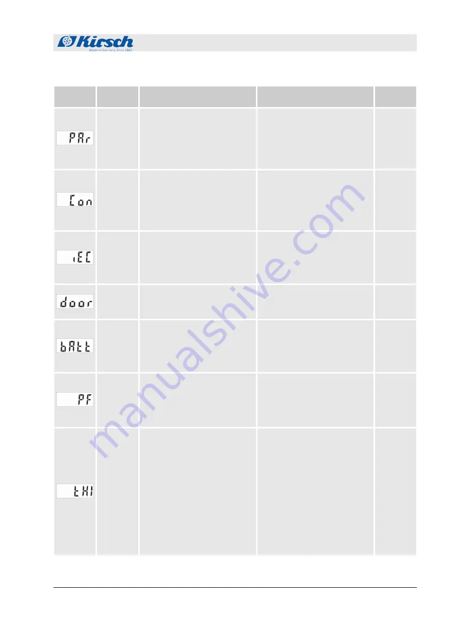
Synchronisation error:

n

Synchronisation error between

control unit and monitoring cir-

cuit.

n

No secured function of the

cooling controller.

n

Set key switch to “0”.

n

Unplug power plug and switch

on again 

Ä

 Chapter 7.1

“Switching on the unit”

on page 49

.

3

3

Connection problem:

n

Synchronisation error between

control unit and monitoring cir-

cuit.

n

No secured function of the

cooling controller.

n

Transfer chilled goods to new

location.

n

Contact the service depart-

ment.

-

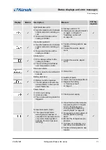
3

Control error:

n

Error during self-test in the

cooling controller.

n

The monitoring circuit takes

over temperature control.

n

Contact the service depart-

ment.

3

Door-open alarm:

n

Door is open for more than 60

seconds.

n

Close door.

3

Battery defective:

n

Battery must be replaced.

n

The temperature documenta-

tion and alarm in the event of

power failure fail.

n

Switch off alarm.

n

Inform the service department.

n

Replace the battery

Ä

 “Service contact”

on page 4

.

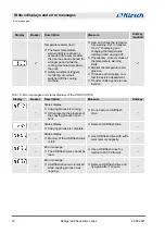
3

Power failure:

n

Unit is not cooling.

n

Alarm is active.

n

The remote warning contact is

triggered.

n

Check power supply.

3

Temperature alarm (high):

n

The upper temperature

warning limit is reached or

exceeded (for example due to

very warm chilled goods or

because the door was open

too long).

n

View and check the tempera-

ture warning limit 

Ä

 Chapter

6.2.2.2 “Displaying and

changing the temperature

warning limits” on page 46

.

n

If necessary, correct values of

the temperature warning

limits.

n

Monitor the temperature pro-

gression.

n

If it does not normalise, con-

tact the service department.

n

Transfer chilled goods to new

location.

3

 Status displays and error messages

Error messages

26.05.2021

Refrigerator/freezer BL series

71

Summary of Contents for 100 03 25C00

Page 1: ...Refrigerator freezer BL series Operating instructions Read instruction manual before starting work ...

Page 2: ... 2 en_GB Philipp KIRSCH GmbH 2021 Philipp KIRSCH GmbH Im Lossenfeld 14 77731 Willstätt Sand GERMANY Telephone 49 781 9227 0 Fax 49 781 9227 200 Email info KIRSCH medical de Internet www KIRSCH medical de 26 05 2021 Refrigerator freezer BL series 2 ...

Page 3: ...llowing target audiences n Owner of the unit n Users of the unit A separate service manual for this unit is available for technical customer service hereafter referred to as service department This manual is valid for the following units Model Factory number from BL 100 PRO ACTIVE 100 03 25000 100 32 25000 BL 176 PRO ACTIVE 170 04 25000 170 30 25000 BL 300 PRO ACTIVE 280 09 25000 280 31 25000 BL 5...

Page 4: ...dical de Business hours n Monday to Thursday 8 00 am to 12 15 pm 1 15 pm to 4 30 pm n Friday 8 00 am to 12 00 pm 1 00 pm to 4 00 pm Service department Philipp Kirsch GmbH Address Im Lossenfeld 14 77731 Willstätt Sand GERMANY Telephone 49 781 9227 777 Fax 49 781 9227 200 Email info kirsch medical de Internet www kirsch medical de Orders are accepted during business hours If you have questions or co...

Page 5: ...n Medical product book n Stock directory n Operating log Other applicable documents Supplemental directives 26 05 2021 Refrigerator freezer BL series 5 ...

Page 6: ...ighting 20 1 7 3 Lockable glass door 20 2 Accessories 21 2 1 GSM module 21 3 Safety 22 3 1 Symbols in this instruction manual 22 3 2 Purpose 23 3 3 Foreseeable misuse 23 3 4 Residual risks 24 3 5 Obligations of the owner 26 3 6 EMC and requirements of the electrical standards 28 3 6 1 Electromagnetic immunity 29 3 6 2 Recommended safety distances 30 3 7 Safety markings 33 3 8 Staff qualification 3...

Page 7: ...48 7 Operation 49 7 1 Switching on the unit 49 7 2 Switching off the unit 50 7 3 Retrieving erasing the temperature memory 50 7 4 Setting up PC KIT NET optional 51 7 5 Stocking the unit 56 8 Cleaning and disinfection 58 9 Maintenance 61 9 1 Safety inspection 61 10 Alarms 65 10 1 Alarm functions 65 10 2 Handling alarms 66 11 Status displays and error messages 67 11 1 Status displays 67 11 2 Error m...

Page 8: ...igerator housing 1 Key switch 2 Display and control unit Ä Chapter 1 2 Display and control elements on page 12 3 Door lock 4 Glass door 5 Adjustable feet 6 Door handle Model BL example Product description Unit overview 26 05 2021 Refrigerator freezer BL series 8 ...

Page 9: ...lood bank refrigerator interior 1 Circulation cooling 2 Support rails 3 Supports 4 Drawer 5 Melt water container 6 Cooling machine Product description Unit overview 26 05 2021 Refrigerator freezer BL series 9 ...

Page 10: ...Key switch 2 Display and control unit Ä Chapter 1 2 Display and control elements on page 12 3 Door lock 4 Adjustable feet 5 Door handle FROSTER BL model example Product description Unit overview 26 05 2021 Refrigerator freezer BL series 10 ...

Page 11: ...Blood plasma freezer interior 1 Circulation cooling 2 Support rails 3 Supports 4 Drawer 5 Melt water container 6 Cooling machine Product description Unit overview 26 05 2021 Refrigerator freezer BL series 11 ...

Page 12: ... power plug 1 Switch on unit n Operate unit n Display and reset unit values for example actual temperature or temperature limits n Confirm alarms P Program unit n Adjust unit for example target values or temperature warning limits n Display parameter lists n Confirm alarms Always operate unit in key position 1 in order to prevent manipulation During normal operation remove key and store it safely ...

Page 13: ...osting Activate additional defrosting Additional light additional defrosting Combination button Activate additional defrosting Switch interior lighting on off permanently SuperFrost Activate SuperFrost function Humidity Adjust humidity Light Switch interior lighting on off permanently Start Start data read out via a PC KIT STICK Cancel Cancel data read out via a PC KIT STICK Unassigned button Unas...

Page 14: ...operation are supplied for each unit in line with the unit specifications n Wire shelves n Drawers The unit is fitted with a lockable unit door Depending on the unit components the following keys are included in delivery n Unit key n Door key for lockable unit door 1 4 Interfaces The unit is equipped with the following interface for connecting additional units hereafter referred to as modules for ...

Page 15: ... drive after the data transfer is completed Ä Error messages and status dis plays of the PC KIT STICK on page 72 1 5 Unit functions 1 5 1 Cooling The unit is equipped with a cooling machine with interior evapo rator for cooling chilled goods After initial commissioning or recommissioning the cooling machine takes a while to cool the interior down to the set target temperature value With circulatio...

Page 16: ...matic defrosting the system ensures that the unit main tains the target temperature value Melt water is conducted into the exterior melt water container and evaporates there When the defrosting process is active the Defrosting LED dis play lights up on the Display In addition to automatic defrosting it is possible to start the defrosting process manually Press button Additional defrosting for four...

Page 17: ... memory is reset automatically when the unit is restarted or reset The temperature memory can be retrieved and erased manually Ä Chapter 7 3 Retrieving erasing the temperature memory on page 50 1 5 5 Temperature monitoring with PC KIT STICK The temperature memory of the unit documents the maximum and minimum temperature values PC KIT STICK is the easiest method of automatic temperature documentati...

Page 18: ...ggered if necessary The battery charges during normal operation and is monitored by an automatic charging system Technical data for the battery n 6 V 4 Ah The battery does not supply the unit The battery only provides power to the tempera ture monitoring The battery does not provide a back up to the unit and therefore ensure that the interior temperature is maintained 1 7 Additional unit component...

Page 19: ...a access for up to 20 clients per server Two server accesses possible Disc type pen recording ther mometer Depending on the model it is either installed in the machine room cover of the refrigerator or freezer or integrated in an additional housing extension Pen recording thermometer for placing in the unit The easiest way to retrofit temperature documentation Temperature measuring range from 25 C...

Page 20: ...nits with a glass door the interior lighting can be permanently switched on or off with the Light button 1 7 3 Lockable glass door Your unit can be equipped with a lockable glass door For more information on installing the glass door contact KIRSCH Interior lighting optional Door lock Product description Additional unit components Lockable glass door 26 05 2021 Refrigerator freezer BL series 20 ...

Page 21: ...e potential free contact n One input for the optional temperature sensor Alarm messages are forwarded to the GSM module via the poten tial free contact connection for remote warning system When the alarm limits are reached an optical and acoustic signal is triggered on the GSM module and an alarm text message is sent The acoustic alarm is acknowledged by sending a confirmation text message to the ...

Page 22: ... and signal word indi cates an immediately hazardous situation that will lead to death or serious injury unless avoided WARNING This combination of symbol and signal word indi cates a potentially hazardous situation that can lead to death or serious injury unless avoided CAUTION This combination of symbol and signal word indi cates a potentially hazardous situation that can lead to minor or slight...

Page 23: ... freezer are medical products of risk class IIa as per EU Regulation 2017 745 Medical Device Regulation 3 3 Foreseeable misuse The unit is not designed for domestic use The unit is used for commercial storage of chilled goods in line with its intended pur pose Do not use the unit to cool warm goods Do not store chilled goods in the unit if their cooling chain was interrupted during delivery or sto...

Page 24: ...ant used in the unit is explosive and pressurised and can cause serious injury if it comes into contact with the eyes or skin During transport and set up do not bend or pierce the tubing and the evaporator Do not damage the surface coat scratching it off for example Wear safety glasses and protective gloves when handling the refrigerant circuit WARNING Danger due to hot surface The marked areas of...

Page 25: ...goods Do not store contaminated chilled goods in the unit After any contamination clean disinfect and sterilise the unit and the chilled goods Clean disinfect and sterilise the unit in line with this instruction manual during operation Comply with the applicable requirements for personal hygiene disinfection and sterilisation CAUTION Danger of damage and injury due to blocked interior ventilation ...

Page 26: ...the unit can overheat and be damaged Do not set up units in close proximity to each other Make sure that the ventilation back and front on the unit is clear Do not cover the cooling machine Allow only qualified staff to install the unit 3 5 Obligations of the owner According to the Medical Devices Act the owner is the natural or legal person entered in the medical product book The owner is obliged...

Page 27: ...ruction n Name of unit officer date of instruction and name of instructed person n Information on safety checks and maintenance n Information on malfunctions and operating errors n Reporting of incidents to the authorities and to KIRSCH The stock directory contains at least the following information n Description sort and type n Lot code or serial number n Year of procurement of the medical produc...

Page 28: ...d to use any accessories other than those described and sold by the manufac turer Spare parts that are not genuine Kirsch spare parts may increase electromagnetic emitted interference or reduce the electromag netic immunity of the unit Portable and mobile HF equipment e g mobile phones can have an impact on electrical med ical equipment The recommended safety dis tances must be maintained The unit...

Page 29: ...ke sure that the unit is used in the appropriate environment Immunity test IEC 60601 test level Con formity Electromagnetic environment guidelines Discharge of static elec tricity DSE IEC 61000 4 2 8 kV contact discharge 15 kV air discharge Yes The underlying surface should be made of wood concrete or ceramic tiles If underlying surface is made of synthetic materials the relative humidity should b...

Page 30: ...s the mains alternating voltage prior to application of the test level 3 6 2 Recommended safety distances Recommended safety distances must be complied with between portable and mobile HF telecommunication devices e g mobile phones and the product which is not life sustaining The product is designed for operation in an electromagnetic envi ronment in which HF disturbances are controlled The custom...

Page 31: ...EC 61000 4 6 3 Vrms 150 kHz to 80 MHz Yes Portable and mobile radio devices must not be used at distances to the product including the lines shorter than the recom mended safety distance as calculated using the transmission frequency specific equa tion Recommended safety distance n d 1 2 P n d 1 2 P 80 MHz to 800 MHz n d 2 3 P 800 MHz to 2 7 GHz 6 Vrms 150 kHz to 80 MHz in ISM and amateur radio fr...

Page 32: ...ty value specified above the unit should be observed to check for normal operation If any abnormal performance is noted further measures may be neces sary such as realigning or moving the product b In the frequency range of 150 kHz to 80 MHz the field strengths should be under 3 V m Banda MHz Serviceb Modulationb Max output W Distance m Immunity test level V m 380 390 TETRA 400 Pulse modula tionb ...

Page 33: ...smitter antenna and the ME UNIT or ME SYSTEM can be reduced to 1 m if necessary A testing distance of 1 m is permitted according to IEC 61000 4 3 a For some services only the uplink frequencies are included b The carrier should be modulated with a square wave signal with a duty cycle of 50 c Alternatively to frequency modulation a 50 pulse modulation at 18 Hz can be used As this does not correspon...

Page 34: ...ly by persons who have the necessary training or skills and experience This manual specifies the staff qualifications for various fields of activity as listed below Inspector The inspector is responsible for the safety inspection according to the Medical Devices Operator Ordinance They must only perform these tasks if they have the necessary qualifications and independence n They must have the tra...

Page 35: ...all other safety related documents n The unit officer has been instructed in the technically correct and safe handling of the unit The unit officer performs the following tasks n The unit officer instructs users in how to handle the unit User The user is the person who uses and operates the unit according to its intended purpose The unit may only be used and operated by trained specialist staff Th...

Page 36: ...ply with either PPE Ordinance 2016 424 or the MDD Directive 93 42 EEC which will be superseded on 27 May 2021 by MDR Regulation 2017 745 Chemical resistant protective gloves Chemical resistant protective gloves protect the hands from aggressive chemicals Protective gloves Protective gloves protect the hands from friction abrasions piercing or deeper injuries as well as from contact with hot sur fa...

Page 37: ...to the hands and feet Wear safety shoes and safety gloves when transporting the unit Transport the unit in an upright position WARNING Danger due to escaping refrigerant The refrigerant used in the unit is explosive and pressurised and can cause serious injury if it comes into contact with the eyes or skin During transport and set up do not bend or pierce the tubing and the evaporator Do not damag...

Page 38: ...section Ä Final decommis sioning of the unit on page 39 1 Transport the unit to the new location Waiting time before recommissioning Once the unit has been transported set up the unit and wait one hour before recommis sioning so that the refrigerant can distribute itself evenly throughout the refrigerant circuit again 2 Recommission the unit as shown in section Ä Putting the unit back into operati...

Page 39: ...n 27 May 2021 by MDR Regulation 2017 745 Before recommissioning clean and disinfect the unit Ä Chapter 8 Cleaning and disinfection on page 58 1 Plug in power plug 2 Insert unit key in key switch 3 Turn unit key to position 1 ð The Display shows the interior temperature 4 Check target temperature and adjust if necessary Ä Chapter 6 2 1 2 Displaying and changing the target temperature on page 43 Lea...

Page 40: ...s and freezers with combus tible refrigerants R600a R290a The basis for calculating the minimum available space at the set up location is the largest fill quan tity of refrigerant in the existing or planned refriger ators For the respective fill quantity of refrigerant see table Ä Chapter 13 2 Technical data on page 78 R600a volume refrigerant fill quantity 8 6 g m R290a volume refrigerant fill qu...

Page 41: ... specified in the technical data and on the type plate 1 Check the connecting cable of the power plug for damage 2 Plug in power plug Set up installation and connection Connecting the unit 26 05 2021 Refrigerator freezer BL series 41 ...

Page 42: ...arm patients Have all tasks performed only by staff qualified for those tasks Keep unauthorised persons away from the working area Commissioning consists of the following activities 1 Clean and disinfect the interior of the unit Ä Chapter 8 Cleaning and disinfection on page 58 2 Switch on the unit Ä Chapter 7 1 Switching on the unit on page 49 3 Program the unit Ä Chapter 6 2 Programming the unit ...

Page 43: ...y KIRSCH The preset value of the target temperature is in accordance with the unit specific standards Do not modify the target value Changes to the target value do not change the temperature warning limits These are adjusted manually Ä Chapter 6 2 1 2 Displaying and changing the target temperature on page 43 6 2 1 2 Displaying and changing the target temperature WARNING Danger due to manipulation ...

Page 44: ...ition P 2 Turn unit key to position P 3 Press and hold button Target temperature 4 Use button Min or Max to set the required target value 5 Turn unit key to position 1 ð The unit regulates the temperature to the specified target value Monitor the temperature progression The unit will not reach the new target value immediately after the change is made Monitor the temperature progression on the Disp...

Page 45: ... the actual temperature and the target tem perature The temperature warning limits are unit specific They can be adapted to the requirements of the chilled goods The values for the temperature warning limits are set at the factory and comply with the valid DIN standards for the unit Recommended temperature warning limits The temperature warning limits must not be the same as the target temperature...

Page 46: ...R BL 530 ULTIMATE FROSTER BL 730 ULTIMATE 55 C 32 C 27 C FROSTER BL 180 PRO ACTIVE FROSTER BL 650 PRO ACTIVE 55 C 41 C 37 C 6 2 2 2 Displaying and changing the temperature warning limits 1 Press button Temperature warning max ð The upper temperature warning limit is shown on the Dis play 2 Press button Temperature warning min ð The lower temperature warning limit is shown on the Dis play Temperatu...

Page 47: ...ng limits on page 46 1 Insert unit key in key switch 2 Turn unit key to position P 3 Press and hold button Temperature warning max 4 Press button Max repeatedly until the value for the new upper temperature warning limit is reached 5 Press button Min repeatedly until the value for the new lower temperature warning limit is reached 6 Turn unit key to position 1 ð The Display shows the current inter...

Page 48: ...nit 4 Inform the unit officer about permitted connections with other medical products and accessories Once instruction is complete record the following information in the medical product book n Name of the unit officer n Date of instruction n Signature of the medical product officer 6 3 2 Handing over the unit The unit has been commissioned Ä Chapter 6 Commissioning on page 42 1 Instruct the unit ...

Page 49: ...ore it so it is protected against unau thorised access 4 Check target temperature and adjust if necessary Ä Chapter 6 2 1 2 Displaying and changing the target temperature on page 43 Lead time of the temperature alarm The temperature alarm is active at the ear liest when the target temperature is reached and at the latest after two hours of unit ope ration 5 Stock the unit when the target temperatu...

Page 50: ...mperature memory The temperature memory records the temperature from the moment the target temperature is reached Restarting the unit resets the temperature memory 1 Press button Max ð The maximum value of the temperature memory is dis played 2 Press button Min ð The minimum value of the temperature memory is dis played 1 Press and hold button Max 2 Press button Reset ð The Display shows The maxim...

Page 51: ...nit after the other to the net work and complete the network connection on the PC The IP address of the unit and the IP address of the standard gateway must be configured in the same address field IP address of unit example 180 160 15 1 IP address of standard gateway example 180 160 15 2 For temperature monitoring via the network the KIRSCH DATANET software version 5 0 or higher must be installed ...

Page 52: ...e Max and Min to set the selected digits of the required IP address ð The number changes on the display in steps of one 8 Release Target temperature ð The first three digits of the IP address have been entered 9 Press Min to select the next parameter 10 Press and hold Target temperature ð The next digits of the IP address are displayed 11 At levels L52 and L53 repeat steps 6 to 10 until the IP add...

Page 53: ...digits of the required subnet mask ð The number changes on the display in steps of one 8 Release Target temperature ð The first three digits of the subnet mask have been entered 9 Press Min to select the next parameter 10 Press and hold Target temperature ð The next digits of the subnet mask are displayed 11 At levels L57 and L58 repeat steps 6 to 10 until the subnet mask has been entered complete...

Page 54: ...e Max and Min to set the selected digits of the required IP address ð The number changes on the display in steps of one 8 Release Target temperature ð The first three digits of the IP address have been entered 9 Press Min to select the next parameter 10 Press and hold Target temperature ð The next digits of the IP address are displayed 11 At levels L62 and L63 repeat steps 6 to 10 until the IP add...

Page 55: ...dust cover from TCP IP output 4 Insert the network cable in the TCP IP output 5 Connect the network cable to the network socket ð The unit has been connected to the network 6 Insert the power plug in the socket 7 Switch on the unit Ä Chapter 7 1 Switching on the unit on page 49 1 Insert unit key in key switch 2 Set unit key to P 3 Press and hold Max and Min simultaneously for four sec onds ð The d...

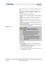
Page 56: ...ject chilled goods to light during the stock transfer Do not place chilled goods near radiators during the stock transfer Make sure that chilled goods are stored in the replacement unit according to the specifications of the relevant manufacturer CAUTION Danger to chilled goods due to contamination A dirty unit can contaminate the stored chilled goods A contamination can damage or destroy the chil...

Page 57: ...AUTION Danger of injury from broken drawers or shelves and falling chilled goods after over loading The carrying capacity of the shelves and drawers is limited If the shelves and drawers are over loaded they can break There is a danger of cut ting injuries caused by broken edges Falling chilled goods can cause bruising Load the drawers and shelves with a maximum of 100 kg m as per DIN 58345 58371 ...

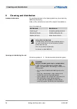
Page 58: ...nfectants If in doubt contact KIRSCH Protective equipment n Chemical resistant protective gloves CAUTION Danger to chilled goods due to contamination A dirty unit can contaminate the stored chilled goods A contamination can damage or destroy the chilled goods Do not store contaminated chilled goods in the unit After any contamination clean disinfect and sterilise the unit and the chilled goods Cle...

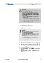
Page 59: ... damage to the electrical system due to unsuitable cleaning agents The unit contains sensitive electronic parts If the electronic parts come into contact with unsuitable cleaning agents this can lead to a loss of function in the unit Use cleaning agents free from sand and acid Do not use chemical solvents Do not bring cleaning agents into contact with electrical parts 2 Clean interior with warm wa...

Page 60: ...care products for painted surfaces Treat the housing with cleaning and care products for stain less steel Cleaning the housing Painted housing Stainless steel housing Cleaning and disinfection 26 05 2021 Refrigerator freezer BL series 60 ...

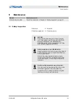
Page 61: ...n 2017 745 Safety inspection as per DIN EN 62353 Safety inspections are used to assess the safety of medical electrical units and medical electrical sys tems or parts thereof Perform the safety inspection before commis sioning during servicing inspection and mainte nance after repairs or when repeat inspections take place Perform safety inspection every two years The unit should be inspected by th...

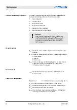
Page 62: ...lowing parts of the unit individually for damage n Door handle n Interior n Door seal 3 If there is damage and functionality is not ensured decom mission the unit and contact the service department Ä Service contact on page 4 Check that the following parts of the unit are functional n Door handle Special tool n Calibrated temperature measuring device 1 Create a simulation of chilled goods for the ...

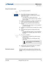
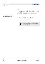
Page 63: ...g spray 6 Wait until the warning limit is exceeded and the buzzer sounds ð The Display alternates between the current temperature and the two error messages upper and lower tempera ture alarm 7 Turn unit key to position 1 ð The test function is completed the electronic delay is switched on again The Display displays the current temperature of the chilled goods The test function is ended automatica...

Page 64: ...ble damage and wear Document the following results of the tests n Date of performance n Results of the individual tests n Other test results The owner is obliged to keep the documenta tion of the safety inspection at least until the next inspection Documenting test results Maintenance Safety inspection 26 05 2021 Refrigerator freezer BL series 64 ...

Page 65: ...the alarm the following measures are required 1 Deactivate buzzer Ä Deactivating the buzzer on page 66 2 Acknowledge alarm Ä Acknowledging the alarm on page 66 3 Inform the service department Ä Service contact on page 4 Tab 9 Alarm functions overview Alarm function Display Buzzer Cause Measure Temperature alarm 3 n The temperature is over the tempera ture warning limit n The remote warning contact...

Page 66: ...act on page 4 Alarm in case of defective display and control unit 3 n The display and control unit is defective n Unplug power plug n Inform the service depart ment Ä Service contact on page 4 10 2 Handling alarms The buzzer sounds 1 Press button Reset ð The buzzer is deactivated 2 Determine cause of the alarm and rectify Otherwise the buzzer will sound again every 30 minutes The buzzer is deactiv...

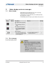
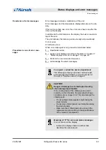
Page 67: ...ne or more alarms have been triggered collective alarm Standby display n The unit is connected to the power grid and the key switch is set to position 0 n Turn key switch to position 1 to switch on the unit 3 11 2 Error messages WARNING Danger due to incorrect repairs or changes Incorrect repairs or changes can cause serious injury e g electric shocks and damage e g fire damage to chilled goods Ha...

Page 68: ...nsured Reduced cooling performance can cause considerable damage to chilled goods Select an alternative storage location for the chilled goods Ensure operating and storage conditions Transfer chilled goods to new location Transferring chilled goods Status displays and error messages Error messages 26 05 2021 Refrigerator freezer BL series 68 ...

Page 69: ...been commissioned and authorised by KIRSCH to provide service for the unit Ä Service contact on page 4 CAUTION Danger of damage due to interrupted cooling chain during stock transfer If the cooling chain of the chilled goods is inter rupted by a stock transfer the prescribed storage conditions are no longer met This can damage the chilled goods Do not subject chilled goods to light during the stoc...

Page 70: ... location n Contact the service depart ment 3 Fan n Fan does not reach required minimum speed after an unit restart n The temperature of the chilled goods can fluctuate n Transfer chilled goods to new location n Contact the service depart ment 3 Fan n Difference between the speeds of the fans is too great n The temperature of the chilled goods can fluctuate n Transfer chilled goods to new location...

Page 71: ...r 3 Battery defective n Battery must be replaced n The temperature documenta tion and alarm in the event of power failure fail n Switch off alarm n Inform the service department n Replace the battery Ä Service contact on page 4 3 Power failure n Unit is not cooling n Alarm is active n The remote warning contact is triggered n Check power supply 3 Temperature alarm high n The upper temperature warn...

Page 72: ...ce department n Transfer chilled goods to new location 3 Tab 12 Error messages and status displays of the PC KIT STICK Display Buzzer Description Measure Unit key Status display n Copying process is running n XX represents the progress of the copying process in per cent n Do not remove USB flash drive Status display n Copying process is complete n Remove USB flash drive Status display n Memory of ...

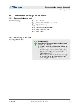
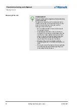
Page 73: ...due to incorrect dis posal of the battery If the battery is disposed of separately proceed as follows Do not damage burn or short circuit the battery Dispose of the battery in accordance with regional regulations If in doubt consult the local communal authority or special disposal specialists regarding envi ronmentally friendly disposal Decommissioning Disposing of the battery Decommissioning and ...

Page 74: ...rigerant for example accidentally enter the environment take suitable measures immedi ately If in doubt contact the responsible com munal authority to report the damage and enquire about the measures to be taken Dispose of the unit in accordance with the regional regulations for electrical and electronic units If in doubt consult the local communal authority or special disposal specialists regardi...

Page 75: ...endix Depending on the model the appendix contains the following appli cable documents n Declaration of conformity n Technical data n Installation drawing Appendix 26 05 2021 Refrigerator freezer BL series 75 ...

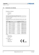
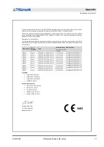
Page 76: ...rial numbers from serial number onwards Basis UDI DI KIRSCH Refrigerator BL 100 PRO ACTIVE 100 32 25000 426068858BLPROACTIVEF4 KIRSCH Refrigerator BL 100 PRO ACTIVE 100 03 25000 426068858BLPROACTIVEF4 KIRSCH Refrigerator BL 176 PRO ACTIVE 170 30 25000 426068858BLPROACTIVEF4 KIRSCH Refrigerator BL 176 PRO ACTIVE 170 04 25000 426068858BLPROACTIVEF4 KIRSCH Refrigerator BL 300 PRO ACTIVE 280 31 25000 ...

Page 77: ...dards EN 61010 1 2010 A1 2019 EN 61010 2 11 2017 EN 60601 1 2 2015 EN IEC 61000 3 2 2014 EN IEC 61000 3 3 2013 Willstätt 20 05 2021 Dr Jochen Kopitzke Managing Director Manufacturer Device category Type Serial numbers from serial number onwards Basis UDI DI KIRSCH Freezer FROSTER BL 178 PRO ACTIVE 170 05 25000 426068858BLFROSTERPAJD KIRSCH Freezer FROSTER BL 180 PRO ACTIVE 180 01 25000 426068858BL...

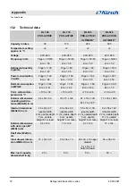
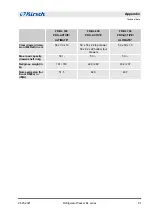
Page 78: ...ure in C 10 to 38 10 to 38 10 to 38 10 to 38 Exterior dimensions including wall dis tance WxDxH in cm 54 x 54 x 82 70 x 77 x 122 67 x 75 x 124 67 x 75 x 131 77 x 76 x 195 5 Interior dimensions WxDxH in cm 44 x 43 x 47 usable width 2 cm usable depth 7 cm usable height 8 cm less 55 x 52 x 60 usable width 3 cm usable depth 9 cm usable height 13 cm less 55 x 51 x 100 usable width 2 cm usable depth 5 c...

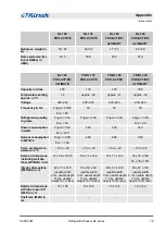
Page 79: ...igen 342 Eco 250 500 453 440 Normal consumption in kWh 24 Frigen XXX Eco 1 56 4 88 6 54 6 59 Perm ambient tem perature in C 10 to 38 10 to 32 10 to 32 10 to 32 Exterior dimensions including wall dis tance WxDxH in cm 77 x 98 x 195 5 70 x 77 x 122 70 x 77 x 122 74 x 78 x 159 74 x 78 x 166 Interior dimensions WxDxH in cm 62 x 77 x 140 usable width 2 cm usable depth 11 cm usable height 13 cm less 55 ...

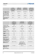
Page 80: ...prox 32 approx 41 approx 32 Voltage 220 240 220 240 220 240 Frequency in Hz 50 50 50 Refrigerant quantity in grams Frigen 620 Frigen 820 Frigen 620 Power consumption in watts 740 990 790 Normal consumption in kWh 24 10 81 14 32 11 1 Perm ambient tem perature in C 10 to 32 10 to 32 10 to 32 Exterior dimensions including wall dis tance WxDxH in cm 77 x 76 x 195 5 83 x 102 x 197 77 x 98 x 195 5 Inter...

Page 81: ...DxH in cm 56 x 39 x 10 59 x 56 x 22 top drawer 59 x 62 x 22 bottom four drawers 56 x 60 x 10 Max load capacity drawer shelf in kg 50 50 50 Net gross weight in kg 161 183 220 260 202 237 Noise emission for Ecool R600a in dB A 51 5 62 3 49 7 Appendix Technical data 26 05 2021 Refrigerator freezer BL series 81 ...

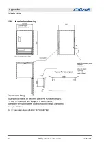
Page 82: ...13 3 Installation drawing Fig 10 Installation drawing for BL 100 PRO ACTIVE Appendix Installation drawing 26 05 2021 Refrigerator freezer BL series 82 ...

Page 83: ...ommissioning 73 Defrosting automatic 16 Defrosting manual 16 Disinfectants 58 Disinfection 58 Display 12 Disposal 73 Documenting test results 64 Door key 14 Drawers 14 E Error messages overview 69 F Final decommissioning 39 Foreseeable misuse 23 Function check 62 H Handover 48 I Images on the display overview 12 Installation 40 Installation drawing 82 Instruction 48 Interfaces 14 Interior fittings...

Page 84: ...isplays overview 67 Stock directory 27 Storage 3 Switching off 50 Switching on 49 Symbols 22 T Target temperature 43 TCP IP module 14 51 Technical data 78 Temperature alarm test 63 Temperature check 62 Temperature display 17 Temperature memory 17 Temperature sensor overview 18 Temperature warning limits overview 46 changing 47 displaying 46 Transport 37 Type plate 33 U Unit door 14 Glass door opti...

Reviews: