7.7 Taking control of the machine
1. When the engine is running, hold the left handlebar, press the
stop switch
and pull the
clutch lever to dislodge the spring latch. Now both clutch and stop levers will be under your
control.
2. Do not release the
stop switch
lever or it will stop the engine. When ready for action,
shift into the required gear and slowly release the clutch lever.
Note
Transmission to the axle and wheels is independent of transmission through the pto to an
attachment.
The advantage of this design is that the most efficient operating rpm of the attachment can
be selected by the throttle setting, and the desired machine movement chosen
independently through a combination of throttle setting and gear selection.
7.8 Gear and PTO engagement
1. Start the engine and take control of the unit. Keep the throttle at moderate speed
setting.
2. Hold the clutch lever (left handlebar) depressed while shifting, and engaging the PTO
lever, and until you are ready to drive.
3. Shift into the lowest forward speed position on the gear speed selector. If the gears will
not engage, release (slip) the clutch just a bit unit the gears mesh.
4. Slowly release the clutch lever and the machine will move forward. If you wish to stop
momentarily without killing the engine or shifting into neutral, depress the clutch lever fully.
7.9 Disengage the clutch
Position 1 and 2 on the gear selector will be available for backing and position 3 will be
locked out.
Select speed, and depress the red reverser lever on right handlebar before engaging the
clutch when going back to forward drive disengages the clutch.
.,5/26.$52,/(1*,1(6/,0,7('
$.LUORVNDU*URXS&RPSDQ\
Summary of Contents for KMW MIN T 8 DLX
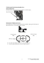
Page 1: ...Dt D E d y...
Page 3: ...5 26 5 2 1 1 6 0 7 LUORVNDU URXS RPSDQ...
Page 7: ......
Page 25: ...5 26 5 2 1 1 6 0 7 LUORVNDU URXS RPSDQ...
Page 27: ...ENGINE BLOCK CRANK CASE 5 26 5 2 1 1 6 0 7 LUORVNDU URXS RPSDQ...
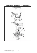
Page 29: ...CYLINDER HEAD ROCKER ARM COVER ASSEMBLY 5 26 5 2 1 1 6 0 7 LUORVNDU URXS RPSDQ...
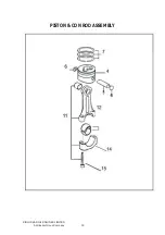
Page 31: ...PISTON CON ROD ASSEMBLY 5 26 5 2 1 1 6 0 7 LUORVNDU URXS RPSDQ...
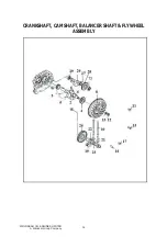
Page 33: ...CRANKSHAFT CAMSHAFT BALANCER SHAFT FLYWHEEL ASSEMBLY 5 26 5 2 1 1 6 0 7 LUORVNDU URXS RPSDQ...
Page 35: ...LUBRICATION AND SPEED CONTROL SYSTEM 5 26 5 2 1 1 6 0 7 LUORVNDU URXS RPSDQ...
Page 45: ...WIND LEADING CASE ASSEMBLY COWLING ASSEMBLY 5 26 5 2 1 1 6 0 7 LUORVNDU URXS RPSDQ...
Page 55: ...REAR COVER ASSEMBLY 5 26 5 2 1 1 6 0 7 LUORVNDU URXS RPSDQ...
Page 57: ...HANDLE BAR MOUNTING ASSEMBLY 5 26 5 2 1 1 6 0 7 LUORVNDU URXS RPSDQ...


