background image


IOM/CPHM/DEC19/01 


            ISSUE DATE:14-12-2019            

Page 

31 | 48 


REVISION NO.1  


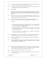
7.2.5 CROSS SECTION DRAWING OF CPHM 11A, 11B, 13:  


PART 

NO. 


DESCRIPTION 


PART 

NO. 

DESCRIPTION 


10500 

PUMP CASING  


27100 

BEARING COVER P.S. 

15100 

ENCLOSED IMPELLER 


31100 

SHAFT SLEEVE 

18001 

PUMP SHAFT 


32000 

KEY FOR IMPELLER 

19000 

CASING WEAR RING SCTION SIDE  


32100 

KEY FOR COUPLING 

19100 

CASING WEAR RING DELIVERY SIDE  


33600 

LOCK NUT  

19200 

IMPELLER RING SUCTION SIDE  


35000 

STUFFING BOX BUSH 

19300 

IMPELLER RING DELIVERY SIDE  


41500 

LOCK WASHER 

22000 

CASING COVER 


43000 

GLAND PACKING 

22700 

LANTERN RING  


44100 

GREASE NIPPLE 

22900 

SPLIT GLAND  


47900 

HELICOIL INSERT  

23602 

LIQUID DEFLECTOR 


48500 

INTERNAL CIRCLIP 

24000 

BEARING HOUSING  


50201 

FELT RING  

25100 

SUPPORT FOOT 


51101 

GASKET FOR CASING 

26300 

ANGULAR CONTACT BALL BRG. D.S. 


51400 

GASKET FOR BEARING 

26400 

CYLINDRICAL ROLLER BRG. P.S. 


51500 

GASKET FOR SLEEVE AND IMPELLER 

27000 

BEARING COVER D.S. 


68200 

GASKET FOR IMPELLER 


Summary of Contents for CPHM

Page 1: ...IOM CPHM DEC19 01 ISSUE DATE 14 12 2019 Page 0 48 REVISION NO 1 INSTRUCTIONS ON INSTALLATION OPERATION AND MAINTENANCE FOR KIRLOSKAR PUMP TYPE CPHM...

Page 2: ...from the date of commissioning of the equipment or 18 months from the date of dispatch from our factory whichever is earlier Our liability in respect of any complaint is limited to replacing part par...

Page 3: ...G 8 GENERAL OUTLINE DIMENSIONS OF CPHM PUMPS CAUTION THIS INSTRUCTION MANUAL COVERS THE GENERAL REQUIREMENTS OF INSTALLATION OPERATION AND MAINTENANCE HOWEVER THE END USER SHOULD REFER TO THE DRAWINGS...

Page 4: ...ed with oil lubrication bearings as a standard supply 2 Pump models with suffix N are modified for improvement in rising nature performance towards shut off 1 2 Description of CPHM pumps KIRLOSKAR CPH...

Page 5: ...o the driver By using spacer type coupling the complete rotating unit can be removed from the volute without removing pump casing or motor and without disconnecting piping connections This also avoids...

Page 6: ...far as lubrication of bearing is concerned other than to replenish the visible reserve supply of the oil in the container Refer Fig 2 3 and 4 2 3 4 2 Method of fitting Screw constant level oiler stem...

Page 7: ...reserve supply of oil in the container as oil is used up 3 Please ensure that Air Groove provided on aluminum body on which plastic container rests is not clogged with dust fiber oil film etc This gro...

Page 8: ...Open the valve on delivery line gradually 3 2 3 Open the cock for pressure gauge connection 3 3 During running the pump check the following things and regulate if necessary 3 3 1 The pump is running s...

Page 9: ...0 34 3 4 3000 11 CPHM 32 16A 1 0 34 3 4 3000 12 CPHM 40 16 1 2 36 4 5 3000 13 CPHM 50 16 1 8 39 9 0 3000 14 CPHM 50 16A 1 8 39 9 0 3000 15 CPHM 65 16 2 8 65 12 0 3000 16 CPHM 80 16 4 0 73 18 0 3000 17...

Page 10: ...45 17 0 290 14 0 1500 48 CPHM 150 40 15 5 285 14 0 1500 49 CPHM 150 43 21 0 300 14 0 1500 50 CPHM 150 52 22 0 435 15 0 1500 NOTE Please contact the supplier or manufacturer if the pump is to be used f...

Page 11: ...o SKF NU309 1 No SKF NU311 1 No SKF NU311 1 No SKF NU311 1 No SKF NU313 1 No NOTES 1 Bearings of SKF make or equivalent are used 2 The bearing arrangement mentioned above are suitable for suction pres...

Page 12: ...be used MANUFACTURER SPEED 1500 RPM 3000 RPM INDIAN OIL SERVOSYSTEM 100 SERVOSYSTEM 68 HINDUSTAN PETROLEUM ENKLO 57 ENKLO 53 Quantity of oil DRIVING UNIT QUANTITY APPROX LITRES 11 1 0 13 1 5 4 3 4 Bea...

Page 13: ...TH 331 ID x 348 OD x 1 TH 411 ID x 432 OD x 1 TH 431 ID x 450 OD x 1 TH 5140001 GASKET FOR BEARING COVER 78 SQ x 1 T 112 x 102 x 1 TH 124 x 134 x 1 TH 5150001 GASKET FOR IMPELLER AND SHAFT SLEEVE 30...

Page 14: ...TH 685 ID x 710 OD x 1 TH 520 ID x 540 OD x 2 TH 5140001 GASKET FOR BEARING COVER 146 x 156 x 1T 140 x 185 x 1 T 5150001 GASKET FOR IMPELLER AND SHAFT SLEEVE 50 OD x 44 ID x 1 TH 74 OD x 69 ID x 1 TH...

Page 15: ...No PUMP SIZE CASING IMPELLER CASING COVER BRG BRKT SHAFT 1 32 13 4 4 4 2 2 40 13 5 5 4 2 3 50 13 6 6 4 2 4 65 13 7 7 4 2 5 32 20 8 8 5 2 6 32 20A 8 9 5 2 7 40 20 9 10 5 2 8 40 20A 10 11 5 2 9 50 20 11...

Page 16: ...ight get contaminated with foreign material or get blackened due to overheating In such cases bearings should be flushed and charged with fresh lubricants 5 2 3 Check the stuffing box leakage normal l...

Page 17: ...tely maintained When the mechanical seal is functioning satisfactorily without any leakage etc the preventive maintenance is not advocated If leakage occurs a thorough check up is needed While fitting...

Page 18: ...ion if any against order Throttle bush for mechanical seals This bush is pressed in the mechanical seal cover This bush gives protection in case of seal s failure Due to the close clearance between bu...

Page 19: ...d in the casing over Turn the bolts evenly through a quarter turn at both sides 6 1 12 Slightly pullout the driving unit till impeller 151 153 clears the pump casing 105 6 1 13 Place this rotating uni...

Page 20: ...e of unit 4 5 7 and 9 take out bearing cover NDE 6 1 21 Take out O ring 523 for bearing housing carefully 7 1 22 Remove the pump half coupling 397 carefully after unscrewing the grub screw CAUTION Cou...

Page 21: ...t temperature 70 to 800 C and then fitted If hot oil is not available use ARBOR PRESS b Slide inboard ball bearing on shaft by hand to make sure that it is square with shaft Press even the inner race...

Page 22: ...from bearing housing lantern bracket 6 2 13 If the casing delivery side is replaced take dimensions of the bore of the ring to check the clearance between impeller and casing wear ring If the impelle...

Page 23: ...5 on the shaft sleeve 311 step e Push impeller 151 153 on shaft till it touches the shaft sleeve f Fix the impeller nut 330 along with helicoil mid grip insert after gasket 682 in between impeller hub...

Page 24: ...cover 4 Mount the rotating part of mechanical seal on the shaft sleeve 315 after pushing on it Tighten grub screws provided on rotating element of mechanical seal after resting seal against step on s...

Page 25: ...e rotation 6 2 23 Fit all the accessories such as sealing water flushing water etc 6 2 24 Fit the support foot 251 to bearing housing 6 2 25 Fit the coupling spacer between pump half and motor half co...

Page 26: ...ID DEFLECTOR BEARING HOUSING LANTERN BRACKET SUPPORT FOOT DEEP GROOVE BALL BEARING DE NDE ANGULAR CONTACT BEARING DE CYLINDRICAL ROLLER BEARING NDE BEARING COVER DE BEARING COVER NDE LIFTING EYE BOLT...

Page 27: ...T FOR GLAND STUDS HEX NUT FOR STUDS RECEIVING LANT BRACKET CAS COVER HEX NUT FOR HEX BOLTS RECEIVING GLAND HEX NUT FOR STUDS RECEIVING BRG HOUSING LANT BRKT STUD FOR PUMP CASING BEARING HOUSING STUD F...

Page 28: ...WEAR RING SUCTION SIDE 32100 KEY FOR COUPLING 19200 IMPELLER RING SUCTION SIDE 33000 IMPELLER NUT 22000 CASING COVER 35000 STUFFING BOX BUSH 22700 LANTERN RING 43000 GLAND PACKING 22900 SPLIT GLAND 4...

Page 29: ...IVERY SIDE 33600 LOCK NUT 19200 IMPELLER RING SUCTION SIDE 35000 STUFFING BOX BUSH 19300 IMPELLER RING DELIVERY SIDE 41500 LOCK WASHER 22000 CASING COVER 43000 GLAND PACKING 22700 LANTERN RING 44100 G...

Page 30: ...WEAR RING DELIVERY SIDE 33600 LOCK NUT 19200 IMPELLER RING SUCTION SIDE 35000 STUFFING BOX BUSH 19300 IMPELLER RING DELIVERY SIDE 41500 LOCK WASHER 22000 CASING COVER 43000 GLAND PACKING 22700 LANTER...

Page 31: ...NG DELIVERY SIDE 33600 LOCK NUT 19200 IMPELLER RING SUCTION SIDE 35000 STUFFING BOX BUSH 19300 IMPELLER RING DELIVERY SIDE 41500 LOCK WASHER 22000 CASING COVER 43000 GLAND PACKING 22700 LANTERN RING 4...

Page 32: ...IVERY SIDE 33600 LOCK NUT 19200 IMPELLER RING SUCTION SIDE 35000 STUFFING BOX BUSH 19300 IMPELLER RING DELIVERY SIDE 41500 LOCK WASHER 22000 CASING COVER 43000 GLAND PACKING 22700 LANTERN RING 44100 G...

Page 33: ...COUPLING 19100 CASING WEAR RING DELIVERY SIDE 33600 LOCK NUT 19200 IMPELLER RING SUCTION SIDE 35000 STUFFING BOX BUSH 19300 IMPELLER RING DELIVERY SIDE 41500 LOCK WASHER 22000 CASING COVER 43000 GLAND...

Page 34: ...IOM CPHM DEC19 01 ISSUE DATE 14 12 2019 Page33 48 REVISIONNO 1 8 GENERAL OUTLINE DIMENSIONS OF CPHM PUMPS...

Page 35: ...IOM CPHM DEC19 01 ISSUE DATE 14 12 2019 Page34 48 REVISIONNO 1...

Page 36: ...IOM CPHM DEC19 01 ISSUE DATE 14 12 2019 Page35 48 REVISIONNO 1...

Page 37: ...dentification impossible This in turn could affect safety and cause difficulty in obtaining spare parts If accidental loss or damage occur contact KBL immediately 1 2 Access to the equipment should be...

Page 38: ...the nameplate and with that on the manual 1 8 Note the Limits of product application permissible use specified in the manual Operation of the equipment beyond these limits will increase the risk from...

Page 39: ...tion covers or packaging in place until removal is necessary for installation If the packaging or suction and discharge covers are removed for inspection purposes replace afterwards to protect the pum...

Page 40: ...maintenance Be cautious and note that other parts of the pump may become hot if a fault is developing Do not operate water pumps in temperatures below freezing point without first checking that the pu...

Page 41: ...pply lockouts where applicable and affix suitable isolation warning signs to prevent inadvertent reconnection In order to avoid the possibility of maintenance personnel inhaling dangerous fumes or vap...

Page 42: ...cking material etc in accordance with local regulations Normally this would involve incineration of liquid waste and controlled landfill of polymerized material Adequacy of suitable crane should be ch...

Page 43: ...Y PIPE SIZE PLEASE CONTACT OUR AUTHORISED DEALER OR NEAREST REGIONAL OFFICE CONCENTRIC TAPER PIECE REDUCED SUCTION PIPE ECCENTRIC TAPER PIECE INCREASED SUCTION PIPE GENERAL INSTRUCTIONS FOR INSTALLATI...

Page 44: ...refore must not be relied upon to maintain the factory alignment Re alignment is necessary after the complete unit has been levelled on the foundation and again after the grout has been set and founda...

Page 45: ...ess on the pump Adequate supports should be given to pipe lines so that weight of the pipe lines does not fall on the pump The use of minimum number of the bends and other fittings will minimise the f...

Page 46: ...ming methods can be used depending on the kind of installation and service involved 1 Liquid level above pump level Pump is set below liquid level of source of supply so that liquid always flows to pu...

Page 47: ...oes not deliver 1 7 8 9 10 11 12 14 15 17 18 19 23 25 26 56 57 58 1 2 3 4 5 6 7 8 9 10 Pump delivers at reduced capacity 11 12 13 14 15 17 18 19 20 21 22 56 57 58 Delivery performance deteriorates 1 3...

Page 48: ...stals from the flow of pumping liquid falling below the temperature limit equilibrium temp 23 Sealing liquid line obstructed 24 Sealing liquid contaminated 25 Lantern ring in the stuffing box is not p...

Page 49: ...ry flow too great 56 Pump unsuitable for parallel operation 57 Type of pump unsuitable 58 Incorrect choice of pump for existing operating conditions 59 Voltage too low power supply overloaded 60 Short...

Reviews: