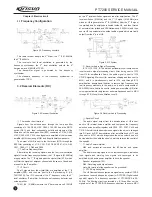
5. 3 Removing the Casing from
the Chassis
1.Remove the knobs;
2.Remove the two knob nuts and
the antenna nut;
3.Remove the two cross head
screws that fix the top cover at the top;
4.Remove the two cross head
screws that fix the aluminum alloy
frame at the bottom by tool;
5.Pull the aluminum alloy frame
out of the casing;
See Figure 5-5
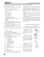
5. 4 Remove the Chassis
from the Main Board
1.Remove the screw;
2.Melt the solder at the antenna
point with a electric soldering iron and
take off the main board;
3.Take away the two screws and
the antenna connector..
See Figure 5-6
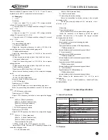
After the aforesaid operations, you can carry out corresponding
service or debugging according to the actual situation.
5-6
Figure
Figure5-5
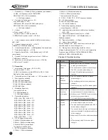
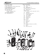
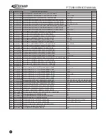
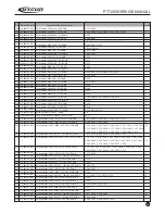
Figure 5-7 Exploded View
PT7200 SERVICE MANUAL
9
Summary of Contents for PT7200-01
Page 1: ...PROFESSIONAL TWO WAY RADIO PT7200 V071215 FM PORTABLE RADIO SERVICE MANUAL ...
Page 29: ...Figure 1 PT7200 Top Board Position Mark Diagram 136 174 ...
Page 30: ......
Page 31: ...Figure 1 PT7200 Top Board Position Mark Diagram 400 470 ...
Page 32: ......
Page 35: ...Figure 7 Schematic Circuit Pane Diagram PT7200 SERVICE MANUAL 26 33 ...


