


18
PT6500 SERVICE MANUAL
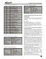
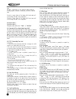
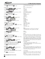
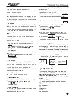
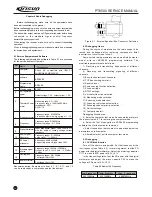
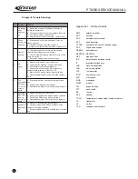
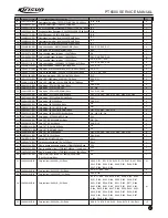
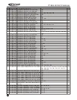
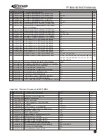
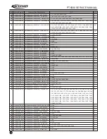
Chapter 8 Trouble Shooting
No.
1
2
3
4
5
Problems
No display
after
switched
on.
Phase
locked loop
unlocked
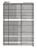
Cannot
transmit.
No
signal
The
transmitting
red light is
on, but no
voice is
heard
Solution
A
Battery power may be insufficient. Recharge or
replace the battery pack.
B
The power switch may be broken, replace the switch.
C
CPU may be broken, replace the IC.
D
Regulator tube Q45 may be broken
replace the IC.
A
Phase locked loop Crystal Oscillator X1 may be
broken, replace it.
B
Oscillator tube may be broken, replace it.
C. Phase locked loop IC2 may be broken, replace the IC.
A
The frequencies of both users are not the same,
select the same frequency channel again.
B
The CTCSS/DCS signaling of both users are not the
same, set it with PC.
C
Beyond the efficient communication range.
A
Make sure the antenna is well connected.
B
Low sensibility, trimming computer test mode
.
C
HF amplifier may be broken, replace it.
D
The squelch level is too high, which makes the
squelch unable to switch on, reset it by PC.
E
Mixer tube Q19 may be broken, replace the tube.
F
Frequency Modulation IC4 may be broken, replace
the IC.
A
Power-amplifier tube no power output, replace the
tube.
B
Replace the microphone if it is broken.
C
Operational Amplifier IC14 may be broken, replace it.
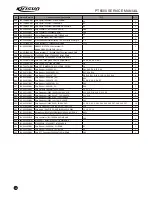
6
7
Receiving
green light
is on, but
no voice is
heard
Abnormal
programmi
ng
A
Replace the speaker if it is broken.
B
Audio power amplifier IC9 may be broken, replace it.
C
Switch Tube Q48 may be broken, replace it.
D
Operational Amplifier IC6 may be broken, replace it.
A
Make sure the wires are well connected.
B
Abnormal output of the RS-232 serial port of the
computer, check the computer .
C
Abnormal connection of MIC and SPK jack, check the
jack.
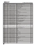
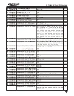
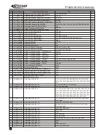
Appendix 1
Abbreviations
AMP amplify, amplifier
ANT antenna
APC automatic power control
BPF band pass filter
CTCSS continuous tone control squelch system
DCS Digital code squelch
DEMOD demodulation
EEPROM EEPROM
HPF high pass filter
IDC instantaneous deviation control
IF intermediate frequency
LED Light-Emitting Diode
LNA low noise amplifier
LPF low pass filter
MCU micro control unit
MIC microphone
MOD modulation
MONI monitor
PLL phase lock loop
PTT push-to-talk
RX receiver
SPK speaker
TCXO Temperature Compensated Crystal Oscillators
TX transmitter
UL un-lock
VCO voltage control oscillator
Summary of Contents for PT6500
Page 1: ...PROFESSIONAL TWO WAY RADIO PT6500 V071208 FM PORTABLE RADIO SERVICE MANOAL Welcome ...
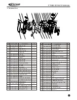
Page 33: ...PT6500 SERVICE MANUAL Figure 1 PT6500 Top Main Board Position Number Diagram 136 174MHz 32 ...
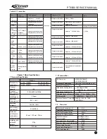
Page 34: ...PT6500 SERVICE MANUAL Figure2 PT6500 Bottom Main Board Position Number Diagram 136 174MHz 33 ...
Page 35: ...Figure 3 400 470MHz PT6500 Top Main Board Position Number Diagram 34 PT6500 SERVICE MANUAL ...
Page 36: ...35 PT6500 SERVICE MANUAL Figure 4 400 470MHz PT6500 Bottom Main Board Position Number Diagram ...
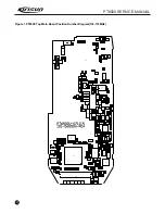
Page 37: ...Figure 5 PT6500 PTT Top Board Position Number Diagram 36 PT6500 SERVICE MANUAL ...
Page 38: ...37 PT6500 SERVICE MANUAL Figure 6 PT6500 PTT BOTTOM Board Position Number Diagram ...


