


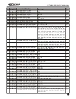
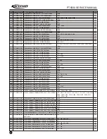
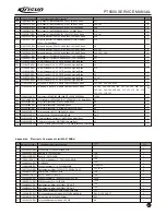
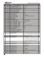
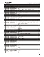

15
6. 3.5
Frequency Deviation Adjustment
A.
Max frequency deviation (HP8920 set at the TX status, filter
set at 50Hz~15kHz): input the audio signal of 160mV,1000Hz at the
MIC port of the radio. Under the computer test mode, select
Max
frequency deviation
to and adjust the digits within 0~64 at the
max, high, medium, low and min frequencies to make the RF
frequency deviation at
4.5kHz.
Adjust the frequency deviation of
narrow band
in the
method above to make the transmitting frequency deviation at
2.2kHz.
B.
5_Tone frequency deviation (HP8920 set at the TX status,
filter set at 50Hz~15kHz): Under the computer test mode, select
5_Tone frequency deviation to enter, select
broadband
and
adjust the digits within 0~255 range to set the frequency deviation
at 4.0kHz.
Adjust the frequency deviation of
narrow band
in the
method above to make the transmitting frequency deviation at
2.0kHz.
C.
DTMF frequency deviation (HP8920 set at the TX status,
filter set at 50Hz~15kHz): Under the computer test mode, select
DTMF frequency deviation
to enter, select
broadband
and
adjust the digits within 0~64 range to set the frequency deviation
at
4.0kHz.
Adjust the frequency deviation of
narrow band
in the
method above to make the transmitting frequency deviation at
2.0kHz.
D.
CTCSS (67Hz) frequency deviation (HP892 set at the TX
status, filter set at 20Hz~300Hz): Under the computer test mode,
select
CTCSS(67Hz) frequency deviation
to enter, select
broadband
and adjust the digits within 0~255 range to set the
frequency deviation at
0.75kHz.
Adjust the frequency deviation of
narrow band
in the
method above to make the transmitting frequency deviation at
0.35kHz.
E.
CTCSS (150Hz) frequency deviation (HP8920 set at the TX
status, filter set at 20Hz~300Hz): Under the computer test mode,
select
CTCSS(150Hz) frequency deviation
to enter, select
broadband
and adjust the digits within 0~255 range to set the
frequency deviation at
0.75kHz.
Adjust the frequency deviation of
narrow band
in the
method above to make the transmitting frequency deviation at
0.35kHz
F.
CTCSS (254.1Hz) frequency deviation (HP8920 set at the TX
status, filter set at 20Hz~300Hz): Under the computer test mode,
select
CTCSS(254.1Hz) frequency deviation
to enter, select
roadband
and adjust the digits within 0~255 range to set the
frequency deviation at
0.75kHz.
Adjust the frequency deviation of
narrow band
in the
method above to make the transmitting frequency deviatio5
6.3.6 Transmitting Low Voltage Alert
(HP8920 set at the TX
status)
Set the voltage of the power supply at 5.8V.
Under the computer test mode, select
transmitting low
voltage
and press adjustment to enter, when the digits are stable,
press Confirm.
6.3.7
Receiver Sensitivity
(HP8920 set at the RX status)
Under the computer test mode, select
Receiver Sensitivity
to enter and respectively adjust 5 frequencies of max. high, medium,
low and min, adjust within 0~255 range to make the frequencies at
the highest sensitivity.
6.3.8
Receiver Squelch Setting
A.
Level 9 broadband squelch (HP8920 set at the RX status):
input the RF signal with adjusted frequency and the amplitude at -
116dBm at the antenna port of the radio. Under the computer test
mode, select
Level 9 broadband squelch
to enter and
respectively adjust f frequencies of max, high, medium, low and min
and make the green LED on when adjusting within the range of
0~255 range.
B.
Level 9 narrowband squelch level (HP8920 set at the RX
status): input the RF signal with adjusted frequency and the
amplitude at -116dBm at the antenna port of the radio. Under the
computer test mode, select
Level 9 narrowband squelch
to
enter and respectively adjust f frequencies of max, high, medium,
low and min and make the green LED on when adjusting within the
range of 0~255 range.
C.
Level 1 broadband squelch (HP8920 set at the RX status):
input the RF signal with adjusted frequency and the amplitude at -
123dBm at the antenna port of the radio. Under the computer test
mode, select
Level 1 broadband squelch
to enter and
respectively
adjust f frequencies of max, high, medium, low and min
and make the green LED on when adjusting within the range of
0~255 range.
D.
Level 1 narrowband squelch level (HP8920 set at the RX
Status): input the RF signal with adjusted frequency and the
amplitude at -123dBm at the antenna port of the radio. Under the
computer test mode, select
Level 1 narrowband Squelch
to
enter and respectively adjust f frequencies of max, high, medium,
low and min and make the green LED on when Adjusting within the
PT6500 SERVICE MANUAL
6.3.2 PLL Frequency Adjustment
(HP8920 set at the TX
status)
Under the computer test mode, select
frequency stability
to
enter, Adjust the TX frequency among 0~255 to the specified value.
(Frequency error less than 200Hz.).
6.3.3 TX Frequency Adjustment
(HP8920 set at the TX status)
A.
Under the computer test mode, select
high power
to
enter and Adjust the TX power among 0~255 to 4W. And watch the
working current and make sure it not higher than 1.7A.
And adjust the max, high, low, min. frequencies in the method
above to make the TX power at 4W for all.
B.
Under the computer test mode, select
medium power
to
enter and Adjust the TX power among 0~255 to 2W. And watch the
working current and make sure it not higher than 1.2A.And adjust
the max, high, low, min. frequencies in the method above to make
the TX power at 2W for all.
C.
Under the computer test mode, select
low power
to
enter and Adjust the TX power among 0~255 to 0.5W. And watch
the working current and make sure it not higher than 1A.And adjust
the max, high, low, min frequencies in the method above to make
the TX power at 0.5W for all.
6.3.4 DCS Transmitted Signal Waveform
(HP8920 set at the TX status, filter set at 20Hz~300Hz)
Under the computer test mode, select
DCS balancing
to
enter, select
broadband
and adjust the digits within the range of
0~255, and watch the signals to make sure the waveforms are
smooth (near square wave) .
Summary of Contents for PT6500
Page 1: ...PROFESSIONAL TWO WAY RADIO PT6500 V071208 FM PORTABLE RADIO SERVICE MANOAL Welcome ...
Page 33: ...PT6500 SERVICE MANUAL Figure 1 PT6500 Top Main Board Position Number Diagram 136 174MHz 32 ...
Page 34: ...PT6500 SERVICE MANUAL Figure2 PT6500 Bottom Main Board Position Number Diagram 136 174MHz 33 ...
Page 35: ...Figure 3 400 470MHz PT6500 Top Main Board Position Number Diagram 34 PT6500 SERVICE MANUAL ...
Page 36: ...35 PT6500 SERVICE MANUAL Figure 4 400 470MHz PT6500 Bottom Main Board Position Number Diagram ...
Page 37: ...Figure 5 PT6500 PTT Top Board Position Number Diagram 36 PT6500 SERVICE MANUAL ...
Page 38: ...37 PT6500 SERVICE MANUAL Figure 6 PT6500 PTT BOTTOM Board Position Number Diagram ...


