ADJUSTMENTS
OPERATING AND ADJUSTING TRU-LOCK VISE SYSTEM cont......
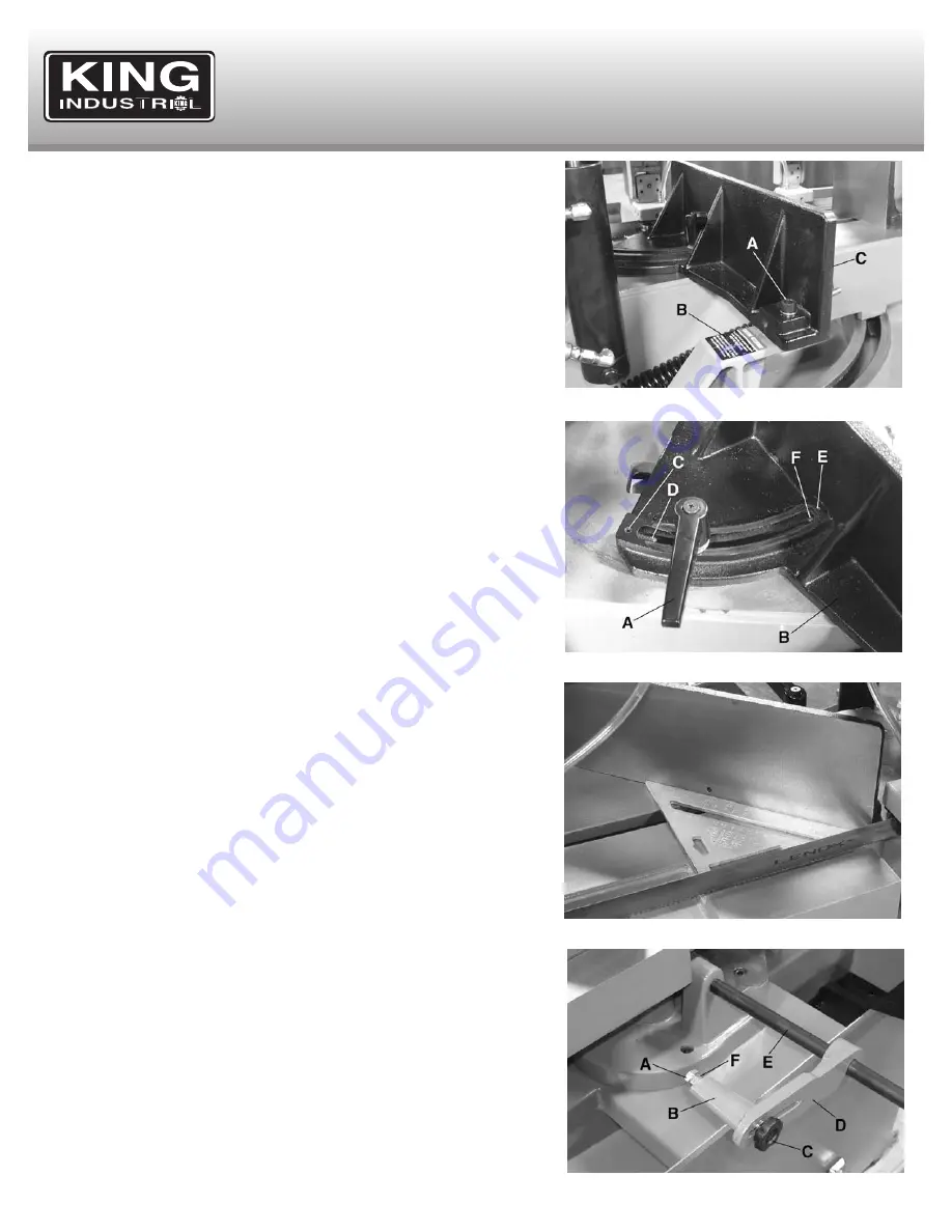
The right side vise (C) Fig.11 comes bolted to a support (B) for transportation
purposes and must be unbolted before it can be used. Loosen and remove
cap screw (A). The vise and pivot table can now be used.
The vise can be adjusted to cut any angle from a straight 90 degree cut-off to
45 degree angle. To adjust the angle of both vise jaws, first loosen the spring
loaded clamp handle (A) Fig.12 on the right side vise jaw (B) and position it to
the desired angle and retighten the spring loaded handle.
Then loosen the hex. shaft (D) Fig.10 on the left side vise jaw (C) with a 19mm
open ended wrench. Place your workpiece on the table and tighten the vise
jaw against it and tighten the hex. shaft to secure angle.
The right side vise jaw comes with positive stops to instantly position the vise
jaw at 90 or 45 degrees. To check and adjust the positive stops, proceed as
follows:
1. To check the 45 degree positive stop, pivot the right side vise jaw all the way
to the left, and lock the spring loaded clamp handle.
2. Place one end of a 45 degree square against the vise jaw and the other end
against the blade and check to see if the vise jaw is 45 degrees to the blade.
See Fig.13.
3. If an adjustment is necessary, loosen clamp handle and then loosen locking
set screw (C) Fig.12 and turn adjusting set screw (D) until the vise jaw is at
45 degrees to the blade. Note: The end of set screw (D) should contact the
stud of clamp handle when vise jaw is 45 degrees to the blade. Then
tighten set screw (C).
4. To check the 90 degree positive stop, pivot the right side vise jaw all the way
to right and lock spring loaded clamp handle.
5. Place one end of a 90 degree square against the vise jaw and the other end
against the blade and check to see if the vise jaw is 90 degrees to the blade.
6. If an adjustment is necessary, loosen clamp handle and then loosen locking
set screw (E) Fig.12 and turn adjusting set screw (F) until the vise jaw is 90
degrees to the blade. Note: Turn set screw (F) from the opposite end,
through the face of the vise jaw. The end of set screw (F) should contact
stud of clamp handle when vise jaw is 90 drgrees to the blade. Then
tighten set screw (E).
ADJUSTING STOCK ADVANCE STOP
The stock advance stop Fig.14 is used mainly when more than one piece of
work is to be cut to the same length. Simply position the stop bolt (A) Fig.14
to the desired distance away from the blade.
The stop bracket (B) may be repositioned up or down by loosening lock knob
(C), the stop arm (D) can also be adjusted in or out on the stop rod (E) by
loosening the stop arm set screw (not shown- it is under the stop arm D).
Fine adjustment to the stop can be made by loosening hex. nut (F) and
turning stop bolt (A).
FIGURE 11
FIGURE 12
FIGURE 13
FIGURE 14


