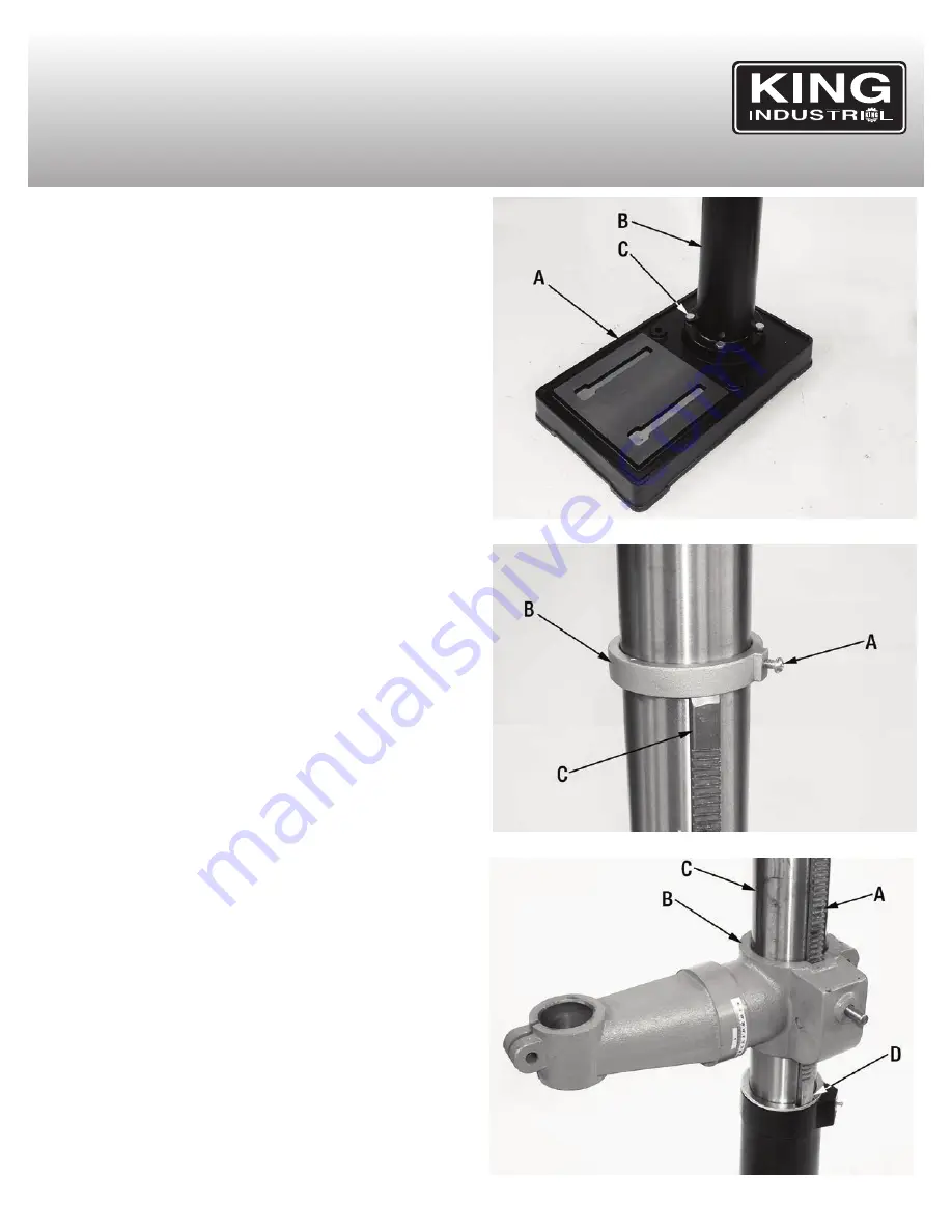
bASE, COLUMN & TAbLE ASSEMbLY
1) Position the base (A) Fig.6 on the floor. Remove the protective
covering and discard.
2) Remove protective sleeve from the column & column support (B) and
discard. Place the column assembly on the base, align the holes in the
column support with the holes in the base.
3) Locate four long hex. bolts from the parts bag.
4) Install a hex. bolt (C) in each hole through the column support and the
base and tighten with the ajustable wrench.
5) Loosen pan head screw (A) Fig.7 in column collar (B) using a Phillips
screwdriver and then remove collar (B) and rack (C) from the column.
6) Slide rack (A) Fig.8 down through the large round opening in the table
support (B). Engage rack in gear mechanism found inside the
opening of the table support.
7) While holding the rack (A) Fig.8 and table support (B) in an engaged
position, slide both down over the column (C). Slide rack down the col-
umn until the rack is positioned against the lower column support (D).
8) Replace column collar (B) Fig.7 and position it bevel side down over
the rack (C). Tighten pan head screw (A) in collar. To let the rack slide
when the table is swung to the left or right around the column, the col-
lar must sit loosely over the rack and should not be angled on the col-
umn. Only tighten pan head screw enough to keep the collar in place,
otherwise the collar may break due to excessive pressure.
FIGURE 6
ASSEMBLY
FIGURE 7
FIGURE 8


