SERVICE SHEET FOR VISTA 60
SERVICE SHEET FOR VISTA 60
DISCONNECT FROM ELECTRICITY SUPPLY BEFORE COMMENCING SERVICE
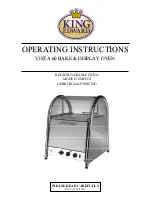
Please note – for directional purposes we always refer to the door side of the oven as the BACK;
the glass side as the FRONT.
1. Replacing top oven bulb:
Access is gained from either side of the top display area. Raise curved
top door; lever off glass cover, unscrew bulb - replace cover ensuring cut-out in cover is over bulb
housing side.
2. Replacing door seal (main oven):
The rectangular shaped oven door seal is kept in place by a clip
at each corner. Simply unclip the original seal and replace with the new part. Due to its shape the
seal cannot be fitted incorrectly.
3. Replacing top oven bulb assembly:
Remove top cover on light housing (4 x TH20 screws). Pull
off wire connectors. Assembly can be removed through top oven after pushing in clamps around
sides. Replace unit and reverse process.
4. Replacing top oven element: (4.1)
Remove front glass (4 x TH20 screws).
(4.2)
Pull off wire
connectors from element terminals. Remove top oven element cover. Unscrew 2 fixing screws on
element plate. Lift out element. Reverse process.
*
Test new element by switching on main switch
and turning top display oven thermostat knob to full, but turn off main oven knob. Wait until heat
is felt in top oven.
5. Replacing thermal cut-out: (5.1)
Remove front glass (4 x TH20 screws).
(5.2)
Remove wire
connectors, unscrew 2 screws and remove fibre washers behind plate. Reverse process.
*
Important
- fibre washer must be replaced between cut-out plate and oven or oven will cut-out
prematurely and disable cooking process. Test oven at
full
temperature and allow to cycle several
times. If whole oven (including lights) go off, cut-off plate needs bending away from oven - retest
when cooled.
6. Replacing main oven fan: (6.1)
Remove element cover inside oven by unscrewing 2 slotted
screws slightly – but do not fully unscrew or remove the screws.
(6.2)
Unscrew central nut
clockwise, remove fan blade. (6
.3)
Remove front glass (4 x TH20 screws).
(6.4)
Pull off wire
connectors from fan motor, unscrew 3 nuts securing fan assembly also 3 brass washers and 3 fibre
washers, remove fan assembly, check condition of fibre washers under fan assembly and if
deteriorated - replace. Reverse Process.
*
When replacing fan assembly ensure there are fibre
washers either side of back plate.
*
Use nut loc or similar on nuts to prevent them from coming
loose!. Test oven by turning green switch on, turn thermostat to mid setting (150-200°C) towards
neon. Allow oven to cycle several times, making sure fan blade does not catch on element cover.
7. Replacing main oven element: (7.1)
Remove front glass (4 x TH20 screws).
(7.2)
Remove wire
connectors from element (below fan).
(7.3)
Remove element cover inside oven by unscrewing 2
slotted screws slightly – but do not fully unscrew or remove the screws.
(7.4)
Remove 2 screws on
element plate.
(7.5)
Pull out element and replace. Reverse process.
*
Test main oven.
8. Replacing thermostat: (8.1)
Remove front glass (4 x TH20 screws).
(8.2)
Carefully open slightly
the 2 clips holding thermostat sensor inside the oven. Move in line with hole the capillary passes
through.
(8.3)
Pull capillary and sensor back through the hole and move out of the way. Pass new
thermostat sensor through hole and put into position in clips. Carefully close clips back to hold
sensor.
*
Leave new capillary slightly slack as not to pull on sensor inside oven. Tidy and secure
new capillary, ensuring it is routed well away from any element and fan motor connections using
cable ties. (
8.4)
Replace front glass panel.
(8.5)
Remove Control Panel (3 screws on top and 4
screws underneath).
(8.6)
Remove thermostat knob and 2 fixing screws. Remove old thermostat
and replace with new unit. Reverse process to return unit to full working order.
*
Test thermostat
by turning knob to approx 200
0
C. Wait until neon goes out and cycles several times before
turning off.

