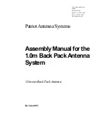
The Faceplate is optional and can be removed as follows:
(Fig. 13)
1. Remove 4 screws from Controller.
2. Slide Faceplate off of Controller.
3. Replace 4 screws.
Page 16
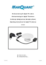
OPTIONAL WALL MOUNT FACEPLATE (INCLUDED)
1. Use the Faceplate as a template to mark and cut out the mounting cavity, and if
necessary, mark and drill the mounting holes
(Fig. 12)
.
2. Mount Faceplate in wall with supplied screws.
Fig. 13
Note:
Depending on the
mounting surface, pilot
holes for the screws
may or may not need to
be drilled.
Fig. 12
Note: If not using the faceplate, see faceplate removal instructions below.
IMPORTANT! Depending on the thickness of the vessel wall, a relief notch may need to
be cut for the cable. THE CABLE MUST NOT BE PINCHED OR BENT
WHEN MOUNTING THE DISPLAY.
Summary of Contents for 9815-RJ
Page 2: ......
Page 15: ...Page 13 9815 RJ 9818 RJ WIRING DIAGRAM Fig 10 IMPORTANT AVOID SHARP BENDS WHEN ROUTING COAX ...
Page 17: ...Page 15 Fig 11 TYPICAL 4 RECEIVER HOOKUP IMPORTANT AVOID SHARP BENDS WHEN ROUTING COAX ...
Page 26: ...Page 24 OPTION 21 RE INITIALIZE and 0 RECALIBRATE ...
Page 27: ...Page 25 ...
Page 31: ......