background image


USER GUIDE


apexDRIVE User Guide 9200162 0v10 

22 


6  Circuit protection 

Each apexDRIVE uses Miniature Circuit Breakers (MCB) to protect the power 
supply to the apexDRIVE control and the connected apexHOIST. 

Additionally fuses are provided to protect the electromagnetic brakes in the 
apexHOIST. 

WARNING!  

DO NOT ATTEMPT TO KEEP AN MCB POWERED ON BY HOLDING THE 

LEVER IN THE ON POSITION 

WARNING!


ALWAYS REPLACE FUSES WITH SAME TYPE AND RATING. SPARE FUSES 

ARE SUPPLIED IN THE ‘BRAKE’ FUSE CARRIER 


6.1 

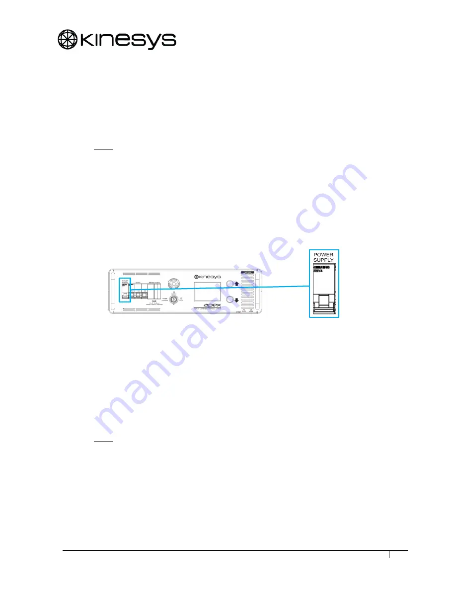
Control ‘POWER SUPPLY’ MCB 


Figure 19 

Power MCB 

The 

POWER SUPPLY

 MCB is used to turn the apexDRIVE on and off.  With the 

MCB lever up the apexDRIVE is on, moving the MCB lever down will turn the 
apexDRIVE off. 

If the power MCB should trip in to the down position try to move the lever up to 
restore power.  If the MCB immediately trips again this indicates a fault. Switch 
over to an alternative apexDRIVE and contact your supplier or Kinesys for support.  

WARNING!  

DO NOT ATTEMPT TO KEEP AN MCB POWERED ON BY HOLDING THE 

LEVER IN THE ON POSITION 


Summary of Contents for apexDRIVE Series

Page 1: ...IVE User Guide 9200162 0v10 1 apexDRIVE Variable Speed Chain Hoist Controller November 2017 Version 0v10 Kinesys Projects Ltd Unit 2 Kempton Gate Business Centre Oldfield Road HAMPTON Middlesex TW12 2...

Page 2: ...USER GUIDE apexDRIVE User Guide 9200162 0v10 2...

Page 3: ...All rights reserved No parts of this manual may be reproduced or transmitted in any form or by any means electrical or mechanical including photocopying recording or by an information storage or retr...

Page 4: ...USER GUIDE apexDRIVE User Guide 9200162 0v10 4 Document Revisions Date Version Number Redmine Edited by Document Changes 24 11 17 0v10 1579 DD BB First customer release...

Page 5: ...the touch screen display LED Light Emitting Diode Limit A set point beyond which a hoist cannot move Loadcell A device used to measure weight Multicore A cable consisting of multiple smaller cables Ov...

Page 6: ...12 3 1 3 Rear Panel 13 4 INSTALLATION 14 4 1 Installation precautions 14 4 1 1 Truss Mount Bracket Primary Support 14 4 1 2 Safety Bond Secondary support 15 4 1 3 Rack Mount Kit 16 5 CONNECTIONS 18 5...

Page 7: ...2 7 4 1 Manual OVERRIDE operation 33 7 4 2 Remote REMOTE operation 34 8 TROUBLESHOOTING GUIDE 35 8 1 Safety system status 35 8 1 1 E stop configuration 36 8 1 2 Safety system status 36 8 1 3 Safety sy...

Page 8: ...ser Guide 9200162 0v10 8 9 4 Periodic testing 43 9 5 Spare parts 43 10 RECALIBRATION OF TOUCHSCREEN 44 11 PRODUCT SPECIFICATION 45 12 DECLARATION OF CONFORMITY 48 13 PACKAGING 49 14 SERVICE END OF LIF...

Page 9: ...0 Figure 17 apexDRIVE and apexHOIST Harting connectors 21 Figure 18 apexHOIST Harting connection on apexDRIVE 21 Figure 19 Power MCB 22 Figure 20 Drive MCB 23 Figure 21 Brake fuses 23 Figure 22 Emerge...

Page 10: ...in ambient temperatures between 5C and 40C The apexDRIVE has an Ingress Protection IP rating of IP30 2 1 1 Do s and Don ts Do not start initial operations before a competent person or a trained speci...

Page 11: ...direction opposite to that which was expected 2 2 Transportation and storage 2 2 1 Condensation The apexDRIVE is designed for indoor use only If the product has been exposed to temperature fluctuation...

Page 12: ...sed to select Override Remote Control or Local operational modes refer to page 25 for more details 5 Emergency Stop button Used to stop all movement in the system in the event of an emergency refer to...

Page 13: ...trol to apexHOIST refer to page 21 for more details 3 Ethernet Safety Connections Ethernet IN and OUT connections used to link apexDRIVE units to form a networked motion control system refer to page 1...

Page 14: ...ting ensure there is enough space within the rack to allow for cables and connections at the rear and the switches and controls at the front Ensure there is adequate ventilation when using the apexDRI...

Page 15: ...lt Verify that the bracket is secured with all four DZUS before attempting to attach to the truss Figure 5 Locking DZUS fasteners 4 1 2 Safety Bond Secondary support The truss mounting kit is supplied...

Page 16: ...cludes 1x pair of front rack ear brackets 2x side mounted rack guides and mounting screws 1x pair rack slide brackets 1 Attach the rack guides to each side fixing on the apexDRIVE using the supplied m...

Page 17: ...attaching rack slides to the rack frame 4 Use the rack guides on the side of apexDRIVE to slide the unit in to the fixed rack slide and line up the rack mount holes in the desired position Figure 10...

Page 18: ...page 36 Ethernet cables must be shielded CAT5e type Kinesys recommends the use of Neutrik Ethercon connectors with ProPlex PCCAT5EP cable Figure 11 Ethercon connector Figure 12 Network connection of...

Page 19: ...DRIVE is fitted with a 5 pole 32A type IEC 60309 CEE power connector and requires a 3 phase mains power supply with neutral 230V N 400V 3 N E A earth ground connection is essential Figure 13 Mains con...

Page 20: ...vary and there is always the possibility that pinouts on cables may not be compatible If in doubt always check cables before use 5 3 1 400V mains input output Figure 15 Mains connection pinout on 400V...

Page 21: ...apexHOIST Figure 17 apexDRIVE and apexHOIST Harting connectors Check the orientation of the connector and socket the connector can only be inserted one way round To prevent accidental disconnection ma...

Page 22: ...SAME TYPE AND RATING SPARE FUSES ARE SUPPLIED IN THE BRAKE FUSE CARRIER 6 1 Control POWER SUPPLY MCB Figure 19 Power MCB The POWER SUPPLY MCB is used to turn the apexDRIVE on and off With the MCB lev...

Page 23: ...ault Switch over to an alternative apexDRIVE and contact your supplier or Kinesys for support WARNING DO NOT ATTEMPT TO KEEP AN MCB POWERED ON BY HOLDING THE LEVER IN THE ON POSITION 6 3 Brake Fuses E...

Page 24: ...fault condition will be displayed on the display Warning When connecting multiple apexDRIVE units with EVO V2 e stop distribution the local emergency stop switch will only stop the locally connected h...

Page 25: ...apexDRIVE to be controlled remotely from motion control software running on a PC or from a connected remote handset Refer to page 34 for more details Local is used to set the apexDRIVE to be controlle...

Page 26: ...R GUIDE apexDRIVE User Guide 9200162 0v10 26 7 3 1 Menu system overview Pressing the Home icon at any time will return the touch screen display to the home screen Figure 24 ApexDRIVE menu system overv...

Page 27: ...ffected by any adjustments to the position where the apexDRIVE is controlled remotely by motion control software Weight is the load on the chain in kg as measured by the integral Loadcell on the apexH...

Page 28: ...on the right of the touch screen to scroll down to view information lower down the screen Home Pressing the Home icon will return the display to the Home screen Note The following Reset icons are ina...

Page 29: ...4 1 Brightness Press this icon to adjust the brightness of the touch screen display Use the slider bar to set the desired brightness of the display Figure 28 Brightness screen 7 3 4 2 Display time ou...

Page 30: ...ress this icon to configure the preferred measurement units for the apexDRIVE display Select Imperial or Metric units using the arrows on either side of the screen Figure 31 Units screen Next press th...

Page 31: ...dless of running conditions speed load etc This value is reset during servicing Total Act RunT Hours total actual usage time overall This value cannot be cleared Temperature displays the current tempe...

Page 32: ...nnected apexHOIST to determine the maximum speed available Once the desired speed of movement is set press and hold the Up or Down manual direction buttons4 to the side of the screen see Figure 33 to...

Page 33: ...tely using Vector or K2 motion control software Alarms Pressing this icon will display the Alarm screen See page 28 for details 7 4 1 Manual OVERRIDE operation When the Mode Key Switch is set to Overr...

Page 34: ...m The PC or laptop running K2 or Vector needs to be connected to one of the Ethernet ports on the Mentor 401 Figure 35 shows an example of how this would be connected Figure 35 Mentor 401 connection l...

Page 35: ...ler status screen Touch the SPLC icon to access the status screen Figure 37 Safety controller status screen This screen lists current status of the apexDRIVE safety PLC and if required allows a manual...

Page 36: ...obal or grouped as required 8 1 2 Safety system status 8 1 2 1 Mode Current safety controller operating mode Reported mode Action required Startup Normal during system startup no action required Initi...

Page 37: ...nt Reverse direction to clear this fault condition Ultimate Up Limit The hoist has reach the limit of its upwards movement as determined by a position set in the control software being used The apexHO...

Page 38: ...safety Mentor 40x series controlled safety system selected No action required if using Kinesys Mentor 40x series safety master If using DC8 v2 then use the icon on Safety Status screen to select EVO S...

Page 39: ...ol software being used The apexHOIST will not move past this point Reverse direction to clear this status condition Safe Down Limit The hoist has reached the limit of its downward movement as determin...

Page 40: ...only used for technical support and repair Access to this menu is not required for normal operation of the apexDRIVE Please contact Kinesys for more details Next from Settings screen Figure 38 Main se...

Page 41: ...sword when the numeric keypad appears Figure 40 Numeric keypad for password entry Note For safety reasons password access is strictly limited to Kinesys and other trained personnel Refer to service ma...

Page 42: ...y dampened cloth if necessary To avoid damaging the surface finishes of the apexDRIVE do NOT use harsh chemicals or abrasive materials when cleaning Filters shall be cleaned in accordance with the pro...

Page 43: ...through with an airline if filter remains dirty it should be replaced 5 Replace filters as required 6 Insert woven filter first then the outer metal mesh Clip the plastic cover back on to retain the...

Page 44: ...ht as shown in Figure 41 Figure 41 Correct orientation of apexDRIVE for screen calibration 1 Confirm key switch is in REMOTE position 2 Check e stop is ON button depressed 3 Press UP and DOWN buttons...

Page 45: ...ion 3 N E 47 63Hz 9A maximum 200 260V N 350 450V 208V version 3 N E 47 63Hz 15A maximum 105 150V N 180 260V Mains power feedthrough5 400V version 32A maximum including apexDRIVE load 200V version 30A...

Page 46: ...display Illuminated UP and DOWN buttons green LED Illuminated e stop button red LED Rear panel indicators Ethernet IN Link Activity green amber LED Ethernet OUT Link Activity green amber LED EVO V2 co...

Page 47: ...dware Refer to Kinesys drawings 9200174 400V or 9200175 208V Rack mount 3U 19 rack mount Truss mount Optional truss mounting kit APM 01 0010 including safety bond Refer to Kinesys drawings 9200174 400...

Page 48: ...USER GUIDE apexDRIVE User Guide 9200162 0v10 48 12 Declaration of Conformity An individual Declaration of Conformity shall be provided with each apexDRIVE...

Page 49: ...2012 19 EU In most regions of the world similar legislation exists to ensure that WEEE is handled separately to maximise reuse of materials and avoidance of landfill 15 Spare parts The following table...

Page 50: ...USER GUIDE apexDRIVE User Guide 9200162 0v10 50 Back Page...

Reviews: