kincrome K15320 Operation And Safety Instructions Download Page 9

UNPACKING AND CLEANING

Unpack the bench drill press and all its parts, and compare against the list below. Do not discard
the carton or any packaging until the bench drill press is completely assembled.

To protect the bench drill press from moisture, a protective coating has been applied to the
machined surfaces. Remove this coating with a soft cloth moistened with kerosene. Do not use
acetone, gasoline, or lacquer thinner to clean. Apply a coat of paste wax to the table and column.
Wipe all parts with a clean, dry cloth.

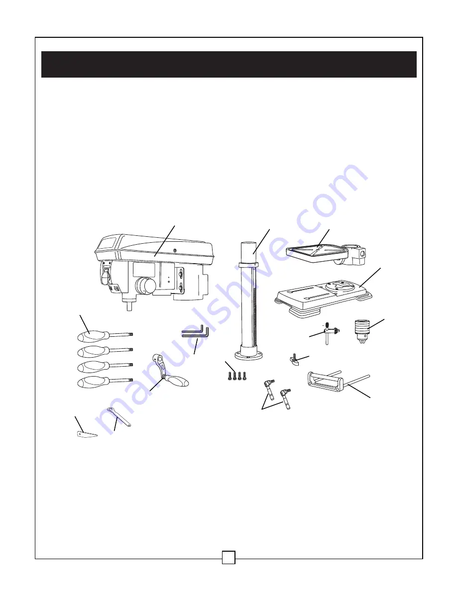
VI. Assembly and adjustments

9

Fig. 2

A

Head/motor assembly

B

Column assembly and table bracket

C

Table

D

Base

E

Chuck

F

Extension wing with integrated rollers

G

Chuck key

H

Wing knobs (2)

I

Table lock handles (2)

J Hex head bolts (4)

K Table crank handle

L Hex keys (2)

M Feed and speed handles (4)

P Table adjustment wrench

Q Wedge

A

J

I

H

B

C

K

Q

P

L

G

E

F

D

M

Summary of Contents for K15320

Page 1: ...PEDESTAL DRILL PRESS Operation and Safety Instructions PART No K15320...

Page 2: ...19 VIII Maintenance 24 IX Troubleshooting 25 X Replacement parts 27 Bench Drill Press with Laser Line MOTOR 220 240 V 50Hz POWER 550W SPEED 450 2500 RPM CHUCK CAPACITY 1 8 5 8 3 16 mm QUILL DIAMETER...

Page 3: ...SK Drilling into materials produces dust 9 ALWAYS remove the power cord plug from the power supply outlet when making adjustments changing parts cleaning or working on the tool 10 AVOID ACCIDENTAL STA...

Page 4: ...XIST IF YOU DELIBERATELY STARE INTO THE BEAM PLEASE OBSERVE ALL SAFETY RULES AS FOLLOWS THE LASER SHALL BE USED AND MAINTAINED IN ACCORDANCE WITH THE MANUFACTURER S INSTRUCTIONS NEVER AIM THE BEAM AT...

Page 5: ...lling into the table 10 ALWAYS stop the drill before removing scrap pieces from the table 11 USE CLAMPS or a vise to secure a workpiece to the table This will prevent the workpiece from rotating with...

Page 6: ...is the equipment grounding conductor If repair or replacement of the electric cord or plug is necessary DO NOT connect the equipment grounding conductor to a live terminal CHECK with a licenced elect...

Page 7: ...d by a qualified person before using it Protect your extension cords from sharp objects excessive heat and damp or wet areas Use a separate electrical circuit for your tools This circuit must not be l...

Page 8: ...ing cover screw H Housing cover I Column J Rack K Crank handle L Column support M Base N Table lock handle O Table lock bolt P Bevel scale Q Laser line ON OFF switch R LED work light switch S Extensio...

Page 9: ...a soft cloth moistened with kerosene Do not use acetone gasoline or lacquer thinner to clean Apply a coat of paste wax to the table and column Wipe all parts with a clean dry cloth VI Assembly and ad...

Page 10: ...en bolts using the adjustable wrench Table to table support bracket Fig 4 1 Place the crank handle 1 onto the shaft 2 of the table bracket so the flat of the shaft is under the set screw 3 Tighten the...

Page 11: ...ress head with the direction of the base and the table 4 Tighten the set screw 4 using a hex key Feed handles Fig 6 1 Insert the three feed handles 1 into the threaded openings on the feed hub 2 2 Man...

Page 12: ...to a stand or workbench with heavy duty fasteners This will prevent the bench drill press from tipping over sliding or walking during operation IMPORTANT If the stand or workbench has a tendency to mo...

Page 13: ...tap the chuck with a rubber mallet not included CAUTION To avoid damaging the chuck make sure the jaws are completely recessed into the chuck Do not use a metal hammer to drive the chuck into the spi...

Page 14: ...e table Fig 13 1 Loosen the bevel lock bolt 1 with the table adjustment wrench provided or with a suitable socket wrench 2 Tilt the table to the desired angle using the bevel scale 2 as a basic guide...

Page 15: ...able 4 approximately 1 2 5 cm below the drill bit 3 Place a combination square 5 on the table as shown placing the long straight edge of the combination square against the drill bit Make sure the dril...

Page 16: ...directly at the laser lines 5 Re tighten the adjustment set screws 3 VI Assembly and adjustments continued 16 WARNING DO NOT STARE DIRECTLY AT THE LASER BEAM A HAZARD MAY EXIST IF YOU DELIBERATELY STA...

Page 17: ...ch 5 is engaged with the raised notch 4 To increase the spindle return tension turn the spring housing counter clockwise To decrease the tension turn the spring housing clockwise 6 Tighten the two hou...

Page 18: ...the belt 2 from the housing cover if it is broken If it is not broken but is too stretched to operate correctly work the belt off the drive motor spindle 3 Then remove the belt from the front spindle...

Page 19: ...w the ON OFF switch on the left The laser switch 5 is located below the ON OFF switch on the right Position the table and workpiece Fig 24 Always place a piece of backup material 1 wood plywood etc on...

Page 20: ...e drill bit will move up or down To stop the drill bit at a pre measured depth 1 Rotate the upper depth knob 2 until the bottom of the knob is aligned with the desired depth mark 5 on the gauge scale...

Page 21: ...ed with the desired depth mark 4 for example 1 on the gauge scale 5 Rotate the upper depth lock knob 1 until it meets the lower depth knob 2 The chuck will be stopped at the distance selected on the d...

Page 22: ...mn If the metal is flat clamp a piece of wood under it to prevent turning If it cannot be laid flat on the table then it should be blocked and clamped Drilling wood Brad point bits are preferred Metal...

Page 23: ...perating raise or lower the speed handle 1 Use the following table to determine the recommended speed for the drill size you are using and the type of material you are to drill While drilling check th...

Page 24: ...ey assembly are greased and permanently sealed Pull the spindle down and oil the spindle sleeve moderately every three months Lubricate the table bracket and locking knobs if they become difficult to...

Page 25: ...just the belt tension See To replace the belt in ADJUSTMENTS Lubricate the spindle See MAINTENANCE section Tighten the retaining nut on the pulley insert Tighten the set screw on the side of the motor...

Page 26: ...e a backup material See Position the table and workpiece in OPERATION Support workpiece using extension wing or clamps See Position the table and workpiece in OPERATION Take to a qualified service tec...

Page 27: ...X Replacement parts 27 K15320 Explosive Drawing...

Page 28: ...ench 15 K15320 15 Hex Bolt M12x25 50 K15320 50 Allen wrench 16 K15320 16 Lock knob 51 K15320 51 Cord power 17 K15320 17 Pan Head Screw 52 K15320 52 Handle knob 18 K15320 18 lock washer 6 53 K15320 53...

Page 29: ...84 Socket set screw 115 K15320 115 Moter Pully Spring 85 K15320 85 Seat Spring 116 K15320 116 Spring cover 86 K15320 86 Filling in Ring 117 K15320 117 V Belt 87 K15320 87 Pan Head ScrewM5x6 118 K1532...

Reviews: