6
10T HYDRAULIC BODY REPAIR KIT
Raising the Ram Plunger (using the Handle (2))
WARNING!: Do not overload this Body Repair Kit. For the Maximum capacity, refer to the specification section for the max working
limits DO NOT commence operation of ram until you are sure of total deflection requirement. Comprehensive
planning for all operations is essential. Ensure the task undertaken falls within the capacity of the pump and any
attachment.
Note:
When adding further extensions to the Ram (4) the maximum rated load is reduced.
1.
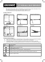
Ensure the unit is assembled for the task at hand (Refer to page 7 for additional assembly combination options).
2.
To operate the hydraulic pump, position it on a stable, leveled surface close to the damaged area/work area. Ensure the
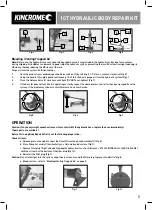
release valve (9) is closed by turning it clockwise (Fig 11), then pump the handle (2) to create pressure (Fig 12).
3.
Turn the release valve (9) counter clockwise to release the pressure (Fig 13).
MAINTENANCE AND STORAGE
Care & Maintenance
Caution: Prior to making any adjustments ensure the pressure is removed from the hydraulic system.
Note: These procedures are in addition to the regular checks and maintenance explained as part of the regular operation of the
hydraulically operated tool.
1.
BEFORE EACH USE, inspect the general condition of the tool. Check for:
a) loose hardware or housing.
b) misalignment or binding of moving parts.
c) cracked or broken parts, and damaged hoses.
d) any other condition that may affect its safe operation.
2.
When not in use, store the equipment horizontaly in a dry location with the Ram (4) fully retracted.
3.
Periodically check the Pump Assembly (1) lever and Ram (4) pistons for signs of rust or corrosion.
Clean exposed areas with a clean oiled cloth.
WARNING!
: Never use sandpaper or abrasive material on these surfaces!
4.
Periodically lubricate the pivot point, axles and hinges with a light lubricating oil as needed, this will help to prevent rust
and assure that pump assemblies move freely.
Periodically lubricate the pivot point, axles and hinges with a light lubricating oil as needed.
5.
With ram fully lowered, set unit in its normal, level position. Remove the oil filler screw to check the hydraulic oil level.
If it is not adequate, add high quality hydraulic jack oil such as Kincromes K12400 (HYDRAULIC JACK OIL 500ML) as
necessary.
WARNING!
DO NOT use brake fluid or any other improper fluid and avoid mixing different types of oil when adding hydraulic oil.
6.
To ensure best performance and longer equipment life, replace complete hydraulic oil at least once a year.
With ram fully lowered, remove the oil filler screw and drain the oil into a suitable container.
Ensure that no dirt gets into the system.
Set the pump in its normal level position, fill with K12400 Kincrome Hydraulic Jack Oil, then replace the oil filler screw.
Note: Dispose of hydraulic oil in accordance with local regulations.
Fig.11
Fig.12
Fig.13
Summary of Contents for K15146 Type 2
Page 10: ...10 10T HYDRAULIC BODY REPAIR KIT NOTES...
Page 11: ...11 10T HYDRAULIC BODY REPAIR KIT...
Page 12: ...www kincrome com au...

