


30
PFX2512_CE
Connecting with the Electronic Load
5
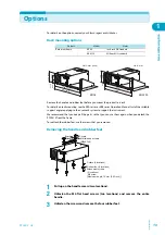
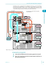
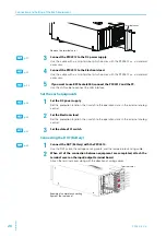
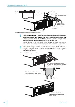
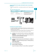
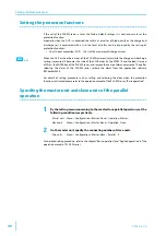
Connect the other end of the cable with the crimp terminal to the output
terminal on the rear panel of the PLZ-4W series. The crimp terminal (M8) with
a red cap is connected to the DC INPUT + terminal, and the crimp terminal
(M8) with a white cap is connected to the DC INPUT -terminal.
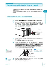
Use the bolt and the nut which comes with a standard accessory of the PLZ-4W
series. Connect the cable against the input terminal in horizontal angle as possible.
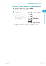
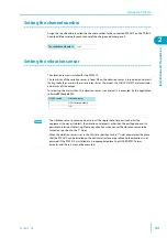
6
Attach the load input terminal cover to the rear pane of the PLZ-4W series
using the lock plate. Fix the pin located inside of the lock plate through the
hole on the cover side.
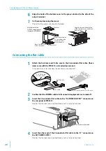
Bolt (M8 x 18)
Spring washer (M8)
Load input terminal cover
Nut (M8)
Cable with crimp
terminal (+: Red)
Cable with crimp terminal
(–: White)
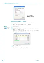
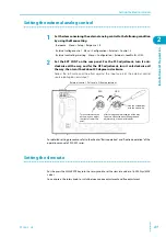
φ
10 line
φ
15 line
φ
20 line
φ
25 line
Cut the sleeve to
match the wire
diameter by using
the gauge as a
reference.
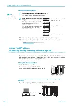
Using the load input terminal cover (Example of PLZ1004W)
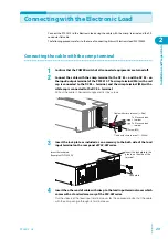
Top view
Move the cover until the edge touches
the panel, and pinch the section indicated
by the arrow to raise the side surface.
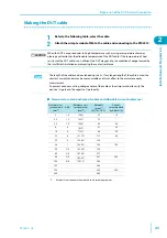
With the side surface of the cover raised,
insert the lock plate pin into the hole.
Check that the left and right lock
plate pins are securely inserted in
the cover holes.
Attachment of the load input terminal cover
(Example of PLZ1004W)
Summary of Contents for PFX2515
Page 10: ...10 PFX2512_CE This page is intentionally blank ...
Page 58: ...58 PFX2512_CE This page is intentionally blank ...
Page 59: ...Specification This chapter contains the PFX2512 specifications and outline drawings ...
Page 86: ...86 PFX2512_CE This page is intentionally blank ...
Page 100: ...100 PFX2512_CE This page is intentionally blank ...
Page 103: ......