background image

Kieback&Peter GmbH & Co. KG
Tempelhofer Weg 50, 12347 Berlin/Germany
Telefon: +49 30 60095-0, Telefax: +49 30 60095-164
www.kieback-peter.de, [email protected]

Datasheet 1.10-65.020-01-EN

RPW301-FTL

Issue 2017-12-20 from V3.02

A

Änderungen vorbehalten - Contents subject to change - Sous réserve de modifications -


Reservado el derecho a modificación


- Wijzigingen

voorbehouden - Con riserva di modifiche - Innehåll som skall ändras - Zmeny vyhradené - Změny vyhrazeny - Zmiany zastrzeżone - Возможны
изменения


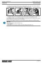
- A változtatások jogát fenntartjuk -


؍⮉ᵚ㓿䙊⸕㘼᭩ࣘⲴᵳ࣋

Product Description

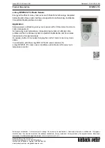
en:key RPW301-FTL Room Sensor

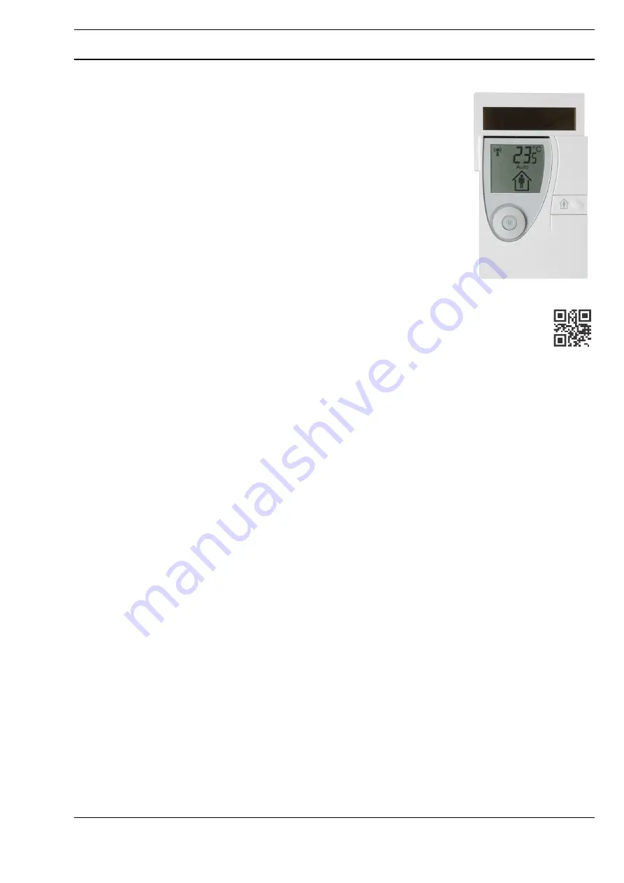
Energy self-sufficient en:key room sensor with SolarFunk technology, integrated 
bidirectional EnOcean radio interface and algorithm for self-learning of utilization 
time profiles/heating profiles in rooms

.

Application

Solar-powered, self-learning en:key room sensor with LCD and smart communi-
cation management
for measuring room temperature, independent generation of utilization time 
profiles and their continuous dynamic adjustment/optimization and for wireless 
transmission of measured values.
Occupancy button for manually changing the comfort mode or economy mode 
status.
In combination with the en:key MD10-FTL-HE valve controller, the 
en:key RPW301-FTL room sensor constitutes a functional unit for easy room 
temperature control.

www.enkey.de

Summary of Contents for RPW301-FTL

Page 1: ...or Energy self sufficient en key room sensor with SolarFunk technology integrated bidirectional EnOcean radio interface and algorithm for self learning of utilization time profiles heating profiles in...

Page 2: ...1 Test installation location function 12 Teaching in the MD10 FTL HE radio partner on the RPW301 FTL 13 Mounting 14 Removal 16 Operating Level 16 Manually switching between comfort and economy mode 16...

Page 3: ...rer The applicable local regulations must be observed when installing and using the device Meaning of the icons WARNING Indicates a hazard of medium risk which can result in death or severe bodily inj...

Page 4: ...ls or cleaning products to clean the device Clean the housing with a moist lint free cloth NOTE The operating modes described here only apply for the self learning en key individual room control lerco...

Page 5: ...ing system Temperature sensor Occupancy sensor Integrated digital sensor Integrated PIR Passive infrared sensor Measuring range 0 50 C Measuring tolerance Typically 0 3 K Display LCD Room temperature...

Page 6: ...nt synchronization process If the radio communication between en key the room and the radio partner is interrupted an internal resynchronization algorithm starts automatically Radio interference is in...

Page 7: ...uilding materials and screening elements e g suspended ceiling elements installation shafts fire doors etc must be taken into consideration during planning NOTE Recommendation Plan radio paths horizon...

Page 8: ...FTL the selected installation location can be changed and optimized at any time without additional effort The installation location must have sufficient lighting using the device in unlit rooms such a...

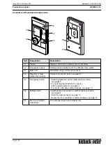
Page 9: ...sor 04 Magnetic contact below the housing To select the service level see page 23 05 Occupancy button Switching between comfort mode economy mode see page16 For switching the RPW301 FTL on off with th...

Page 10: ...dio partners can be registered registration status active 06 Information field Display of the room temperature time date initial dis play can be configured or messages 07 Auto Learned utilization time...

Page 11: ...valuating the installation location NOTE The Test installation location function remains active as long as the text InSt is displayed see page 12 NOTE The en key room sensor automatically switches off...

Page 12: ...d commissioned NOTE The en key room sensor automatically switches off if a radio partner has not been taught in after 15 minutes NOTE If the energy storage unit is empty the Sun icon will not appear e...

Page 13: ...e number of taught in valve controllers is displayed after approx 15 s The Antenna icon appears after another 45 s Data has been exchanged between the radio partners All valve controllers must be taug...

Page 14: ...e of delivery of the room sensor WARNING Flush mounted cabling and piping at the installation location electricity gas water Cabling and piping can be damaged by drilling Check the installation locati...

Page 15: ...ll mounting Flexible screw mounting 1 bar 2 adhesive numbers Wall mounting Flexible adhesive mounting with double sided transparent adhesive strips NOTE For a permanent connection remove any dust and...

Page 16: ...the display Changing from comfort mode to economy mode economy mode is active for 4 hours The utilization time profile is then active again and the Auto icon appears on the display Example 1 Comfort...

Page 17: ...mically adjusted and optimized This is displayed by the comfort mode or economy mode icons The Auto icon also appears in the display Presence absence is recorded by the occupancy sensor in order to le...

Page 18: ...e the Occupancy button The Set vacation menu appears in the display Hold down the Occupancy button for 5 seconds The value being set flashes Briefly press the Occupancy button to set the duration of t...

Page 19: ...on once only to confirm the hour displayed or press it several times hold it down until the desired set value is reached Release the Occupancy button The next value to be set will start to flash after...

Page 20: ...x 3 seconds the display switches to the initial display If 12 hour display is active an additional P is displayed during the afternoon and evening hours Default setting 24h Switching the temperature s...

Page 21: ...nfig menu ConF Hold down the Occupancy button for 5 seconds Release the Occupancy button The Set vacation menu appears in the display Briefly press the Occupancy button repeatedly to select the dISP f...

Page 22: ...ccession If you do not take any other actions the display will return to the initial display after 5 seconds Status message The status message is displayed Further information can be found on page 25...

Page 23: ...igure The room sensor switches to the service level Briefly press the Occupancy button repeatedly and the system will offer you the aforementioned functions one after the other If you do not take any...

Page 24: ...deleted and the room sensor is reset to the default settings Software version display Briefly press the Occupancy button repeatedly to select the Software version display function Displays the softwa...

Page 25: ...e Antenna Prog Flashes On Valve controllers can be registered Antenna 1 Er01 On On Radio connection partly interrupted 1 hour At least one valve controller is being received Antenna 1 Er01 Off On Radi...

Page 26: ...utilization time profile permanently switches to economy mode and the icon appears on the display If the Occupancy button is pressed after a longer absence or if the room sensor detects room occupancy...

Page 27: ...continues to appear It should be checked by an authorized service technician NOTE If the room sensor transmission function is malfunctioning the valve controllers continuously operate in comfort mode...

Page 28: ...A Page 28 28 Product Description RPW301 FTL Datasheet 1 10 65 020 01 EN Issue 2017 12 20 from V3 02...

Reviews: