


Assembly Instructions
Backbone
®
Media Platform
August 2014
Assemble units as described herein only. To do otherwise
may result in instability. All screws, nuts and bolts must be
tightened securely and must be checked periodically after
assembly. Failure to assemble properly, or to secure parts
may result in assembly failure and personal injury.
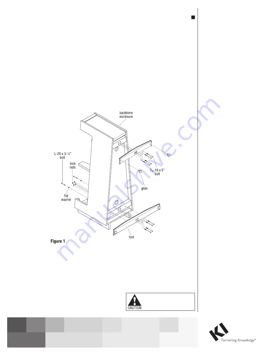
1. Remove the Backbone
enclosure from pallet, taking
care not to damage the bottom
edges. Then remove support
feet, access door, adjustable
glides and hardware kit
#47.0815 from inside the
enclosure.
2. Place packaging foam or
cardboard onto the floor for
protection. As illustrated,
carefully place the enclosure
unit onto the protective
material and stand it up on its
back end, the wider side of the
enclosure unit (Figure 1).
3. Install the longer 38” foot
to the lower, wider end of
the enclosure bottom. First
locate two
1
/
4
-20 x 3-
1
/
2
”
self-threading countersink
headed screws and add a flat
washer to each. From inside
the Backbone enclosure, insert
the two
1
/
4
-20 x 3-
1
/
2
” self
threading screws with washers
through the enclosure and into
the threaded outer holes on the
38” foot. Do not fully tighten
at this time. Next, locate and
insert the four
5
/
16
–18 x 5”
bolts through the bottom,
center of the foot and into the
enclosure from the outside.
Twist on four locking nuts,
but do not fully tighten at this
time. Leave all fasteners loose
until all bolts are attached
(Figure 1).
4. Attach the shorter foot to the
underside of the enclosure, as
done above with the 38” foot,
by using only four
5
/
16
–18 x 5”
bolts and locking nuts. Do not
tighten at this time (Figure 1).
5. Square the feet to the units
support cross members and
tighten all fasteners. Then
insert the four adjustable
threaded glides into the feet
(Figure 1).
6. Carefully lower the unit on to
the support feet and adjust
leveling glides if necessary.
Note:
If Monitor Support Panel
(optional) is not included, skip
now to step 9.


