


70
3.2.4.5 Wire connection
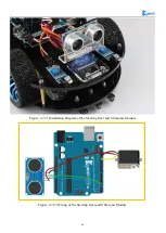
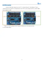
As shown in the below figure, the servo's "S" is connected to pin 13, the ultrasonic "Trlg" is
connected to pin 2, the "Echo" is connected to pin 3, the "VCC" pin is connected to VCC, and the "GND"
pin is connected to GND.
Figure 3.2.33 Wiring diagram of steering gear, ultrasonic wave and expansion board
3.2.4.6 Software design
Summary of Contents for Hummer-Bot-1.0
Page 1: ...Hummer Bot 1 0 Instruction Manual V 2 0 ...
Page 18: ...15 Step4 You need to install motors Figure 3 1 5 Schematic diagram of motor installation ...
Page 50: ...47 Figure 3 2 15 Diagram of Data without Obstacles ...
Page 83: ...80 Test code Path hummer bot Lesson ModuleDemo IrkeyPressed IrkeyPressed ino ...


