3
Determining the Extent of Signal Degradation with Acquisition Probes
20
Keysight U4421A MIPI D-PHY Analyzer and Exerciser Hardware and Probing Guide
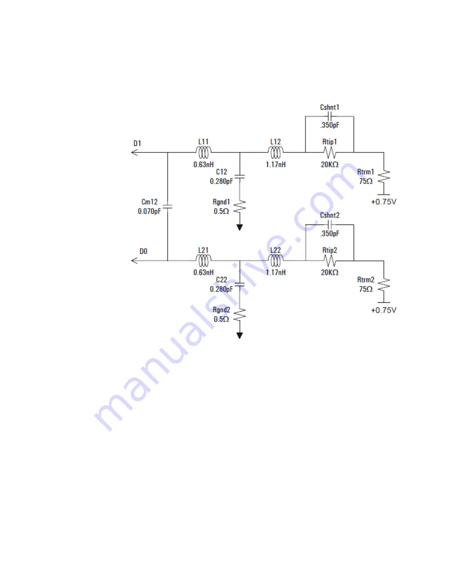
Probe Load Model for E5405A Soft Touch Probe
Page 1: ...Keysight U4421A MIPI D PHY Protocol Analyzer and Exerciser Hardware and Probing Guide...
Page 2: ...es the Software to U S gov ernment customers under its standard com mercial license which is embodied in its End User License Agreement EULA a copy of which can be found at http www key sight com find...
Page 3: ...It is designed to operate at a maximum relative humidity of 95 and at altitudes of up to 2000 meters Refer to the specifications tables for the ac mains voltage requirements and ambient operating temp...
Page 4: ...ove the Instrument Cover Operating personnel must not remove instrument covers Component replacement and internal adjustments must be made only by qualified personnel Instruments that appear damaged o...
Page 5: ...module and host computer and how to obtain and install the associated software components see Keysight AXIe based Logic Analysis and Protocol Test Modules Installation Guide This guide is available o...
Page 6: ...6 Keysight U4421A MIPI D PHY Analyzer and Exerciser Hardware and Probing Guide...
Page 7: ...ion Probes Probe Load Model for E5405A Soft Touch Probe 20 Probe Load Model for E5381A Flying Probe 21 4 Setting up an E5381A Differential Flying Lead Probe Configuration for U4421A Module E5381A Diff...
Page 8: ...9 Probe and Retention Module Dimensions 39 Probe Pad Layout Footprint Dimensions 41 Pinout Details for E5405A Probe 42 Suggested Signal Routing with E5405A Probe 43 Installing a Retention Module on th...
Page 9: ...ht U4421A MIPI D PHY Analyzer and Exerciser Hardware and Probing Guide 1 U4421A Module U4421A Module Hardware Components 10 This chapter provides information on the hardware components of the U4421A m...
Page 10: ...ackets using various Keysight tools and viewers available in the Keysight Logic and Protocol Analyzer GUI For information on Keysight AXIe chassis U4421A module how to set up the chassis module and ho...
Page 11: ...eans that the lane is in the Escape mode and data is being transmitted from slave to master Escape mode includes bus turn around BTA escape mode data transmission and ULPM request Off This means that...
Page 12: ...input voltage should not exceed 3 3 V Trigger Out and 10 MHz Out have nominal output level of 2 0 V with 20 ns minimum pulse width Minimum Trigger In duration is 20 ns OOS Out of Service LED Indicate...
Page 13: ...2 Setting up a Stimulus Probe Configuration for U4421A Module U4422A SMA Stimulus Probe Introduction 14 Connecting the U4422A Probe to the U4421A module and DUT 16 This chapter provides information on...
Page 14: ...axial cables Table 1 Labelling and color coding of the coaxial cables of U4422A probe Module Connector Coaxial cables with SMA Connectors Label Color Coding Signal Direction Description Usage of cable...
Page 15: ...r U4421A Module 2 Refp Red To U4421A module Emulator reference clock input positive signal Refn Red with white To U4421A module Emulator reference clock input negative signal Vsen White To U4421A modu...
Page 16: ...negative signals labelled D0p and D0n ii For a x2 x4 link connect the additional cables for D Phy data 1 to 3 lane positive and negative signals labelled D1p and D1n D2p and D2n and D3p and D3n You ma...
Page 17: ...wo methods From a piece of test equipment such as a signal generator By probing a signal on the DUT Place 1K Ohm isolation resistor in series with the Ref pn signals Refp and Refn input signals specif...
Page 18: ...2 Setting up a Stimulus Probe Configuration for U4421A Module 18 Keysight U4421A MIPI D PHY Analyzer and Exerciser Hardware and Probing Guide...
Page 19: ...the probing method s to be used The amount of signal degradation that a target system can tolerate can vary widely depending on signal rise times design margins and system noise The following table p...
Page 20: ...3 Determining the Extent of Signal Degradation with Acquisition Probes 20 Keysight U4421A MIPI D PHY Analyzer and Exerciser Hardware and Probing Guide Probe Load Model for E5405A Soft Touch Probe...
Page 21: ...robes have an input impedance which varies with frequency and depends on which probe attachment accessories see page 30 are being used to connect the flying leads of the probe to DUT The following scr...
Page 22: ...s 22 Keysight U4421A MIPI D PHY Analyzer and Exerciser Hardware and Probing Guide Figure 4 Equivalent probe load model when using the 3 pin header as the attachment accessory Figure 5 Equivalent probe...
Page 23: ...D PHY Analyzer and Exerciser Hardware and Probing Guide 23 Determining the Extent of Signal Degradation with Acquisition Probes 3 Figure 6 Equivalent probe load model when using the damped wire as the...
Page 24: ...3 Determining the Extent of Signal Degradation with Acquisition Probes 24 Keysight U4421A MIPI D PHY Analyzer and Exerciser Hardware and Probing Guide...
Page 25: ...Lead Probe Configuration for U4421A Module E5381A Differential Flying Lead Probe Introduction 26 Probe Accessories 30 Connecting the E5381A Probe to the U4421A Module and DUT 36 This chapter provides...
Page 26: ...d probe accessories to the DUT This allows flexible connections to individual signals When to use an E5381A Flying Lead Probe An E5381A flying lead probe is suitable for use in situations such as When...
Page 27: ...d Cables This component connects the E5381A probe to the DUT via the attachment accessories supplied with the probe There are 17 flying lead cables in each probe Each flying lead cable when connected...
Page 28: ...ve and negative signals Two flying leads for probing D PHY data lane 0 positive and negative signals One flying lead each for probing D PHY data lane 1 2 and 3 if used Channel Number of the flying lea...
Page 29: ...Data Lane 0 diff Ch 1 Probe differentially Connect the Positive Light grey cable of the flying lead to the D0p signal and Negative Dark grey cable of the flying lead to the D0n signal Data Lane 1 Ch 4...
Page 30: ...81A flying lead tip Probe Accessories Various accessories are provided with the E5381A probe to connect the flying leads of the probe to the DUT The usage of these accessories vary based on the type o...
Page 31: ...81 82104 34 Recommended for loading during PC board assembly or hand soldering in place at a later time Socket Adapters E5381 82102 34 Recommended if you already have 0 635 mm 0 025 inch pins on 2 54...
Page 32: ...te how to use a particular probe accessory to connect the E5381A probe s flying leads to the DUT Connecting Coaxial Tip Resistors Figure 10 Coaxial Tip Resistor used as the probe attachment accessory...
Page 33: ...ide by side as follows Figure 12 Using two 3 pin headers side by side to probe Data Lane 0 p and Data Lane 0 n There must be 0 1 inch spacing between the 3 pin headers placed side by side For other D...
Page 34: ...lyzer and Exerciser Hardware and Probing Guide Connecting Socket Adapters Figure 13 Socket Adapter used as the probe attachment accessory NOTE You can connect multiple socket adapters side by side to...
Page 35: ...Y Analyzer and Exerciser Hardware and Probing Guide 35 Setting up an E5381A Differential Flying Lead Probe Configuration for U4421A Module 4 Connecting Damped Wires Figure 14 Damped wire used as the p...
Page 36: ...he appropriate flying lead cables of the probe to the accessories attached to the DUT in the previous step Refer to the topic D PHY Signals to Flying Leads Mapping on page 28 to know which flying lead...
Page 37: ...etting up an E5405A Soft Touch Midbus Probe Configuration for U4421A Module E5405A Soft Touch Midbus Probe Introduction 38 Designing the Footprint on the DUT 39 Installing a Retention Module on the Ta...
Page 38: ...e page 39 2 Installing the E5403A retention module on the target system board see page 44 3 Connecting the E5405A probe to the DUT and U4421A module see page 46 When to use an E5405A Probe An E5405A p...
Page 39: ...place the board between the DUT and a dynamic termination board such as the University of New Hampshire InterOperabilty Laboratory UNH IOL MIPI DPhy Reference Termination Board Designing the Footprint...
Page 40: ...Setting up an E5405A Soft Touch Midbus Probe Configuration for U4421A Module 40 Keysight U4421A MIPI D PHY Analyzer and Exerciser Hardware and Probing Guide Figure 18 E5403A retention module dimension...
Page 41: ...ew footprint dimensions drawing notes below Drawing notes 1 Maintain a solder mask web between pads when traces are routed between the pads on the same layer The solder mask may not encroach onto the...
Page 42: ...is footprint is compatible with Keysight model number E5403A retention module 5 Plated through hole should not be tied to ground plane for thermal relief Pinout Details for E5405A Probe The following...
Page 43: ...le 5 Suggested Signal Routing with E5405A Probe The E5405A probe has two rows of compliant pins to make contact with pads that you laid down on the surface of the target system board The following fig...
Page 44: ...etention modules are supplied with each E5405A probe If you need more retention modules than the number of modules included in the probe shipment you can order the part number E5403A that contains a s...
Page 45: ...Keysight U4421A MIPI D PHY Analyzer and Exerciser Hardware and Probing Guide 45 Setting up an E5405A Soft Touch Midbus Probe Configuration for U4421A Module 5...
Page 46: ...e location of the keying feature on the E5405A probe tip and the matching feature on the E5403A retention module that you mounted on the DUT circuit board b Orient the probe so that the keying feature...
Page 47: ...sions 39 E5405A probe load model 20 E5405A probe pinout 42 E5405A signal routing 43 exerciser port 11 external reference clock 16 F flying lead cable color coding 28 flying lead colors 27 flying lead...
Page 48: ...Index 48 Keysight U4421A MIPI D PHY Analyzer and Exerciser Hardware and Probing Guide...