


6
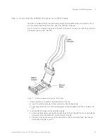
Setting up the W6602A Interposer
60
Keysight W6600A-series LPDDR4 BGA Interposers Installation Guide
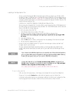
W6602A Clock Qualifier and RESET Connections
The table below describes the connections to be established between the U4207A clock connection
flying leads and the CKE and RESET pin headers of the W6602A clock connectors.
NOTE
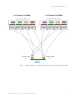
The hardware configurations change depending on the logic analyzer software configuration in
which the interposer is being used. The connectivity is therefore segregated based on a
16-bits channels configurations and a 32-bits channels configuration.
Signals
For Channel A in a 16-bits DRAM
configuration
For Channel B in a 16-bits DRAM
configuration
For a single 32-bits channels DRAM
configuration
CKE1_A or CKE2_A
and
CKE1_B or CKE2_B
Use the orange flying lead of the
U4207A cable that you connected to
J1 on the W6602A interposer.
Connect this orange flying lead to
either CKE1_A or CKE2_A pin header
(J3 or J5 connector) of W6602A.
(In the Channel A 16-bits software
configuration, this signal is named
CKE1.)
Use the purple flying lead of the
U4207A cable that you connected to
J1 on the W6602A interposer.
Connect this purple flying lead to
either CKE1_B or CKE2_B pin header
(J4 or J7 connector) of W6602A.
(In the Channel B 16-bits software
configuration, this signal is named
CKE1.)
Use the orange flying lead of the U4207A cable
that you connected to J1 on the W6602A
interposer.
Connect this orange flying lead to either CKE1_A
or CKE2_A pin header (J3 or J5 connector) of
W6602A.
(In the 32-bits single channel software
configuration, this signal is named CKE1.)
RESET
Use the purple flying lead of the
U4207A cable that you connected to
J2 on the W6602A interposer.
Connect this purple flying lead to the
RESET pin header (J6 connector) of
W6602A.
Use the orange flying lead of the
U4207A cable that you connected to
J2 on the W6602A interposer.
Connect this orange flying lead to
the RESET pin header (J6
connector) of W6602A.
Use the purple flying lead of the U4207A cable
that you connected to J2 on the W6602A
interposer.
Connect this purple flying lead to the RESET pin
header (J6 connector) of W6602A.
Summary of Contents for LPDDR4
Page 1: ...Keysight W6600A Series LPDDR4 BGA Interposers Installation Guide ...
Page 4: ...4 Keysight W6600A series LPDDR4 BGA Interposers Installation Guide ...
Page 8: ...8 Keysight W6600A series LPDDR4 BGA Interposers Installation Guide Contents ...
Page 10: ...1 Introduction 10 Keysight W6600A series LPDDR4 BGA Interposers Installation Guide ...
Page 78: ...Index 78 Keysight W6600A series LPDDR4 BGA Interposers Installation Guide ...
Page 79: ...Keysight W6600A series LPDDR4 BGA Interposers Installation Guide 79 ...


