


Keysight W6600A-series LPDDR4 BGA Interposers Installation Guide
59
Setting up the W6602A Interposer
6
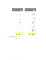
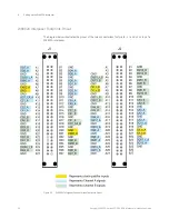
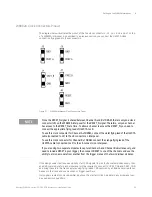
W6602A Clock Connectors Pinout
The diagram below illustrates the pinout of the five clock connectors - J3, J4, J5, J6, and J7 on top
of a W6602A interposer. As described in a previous section, you connect the U4207A clock
connection flying leads to these connectors.
Figure 21
W6602A Interposer Clock Connectors Pinout
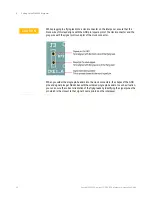
If the design under test requires visibility of all CKE signals from both channels simultaneously, then
an additional module for each module set will be required to connect to CKE2_CHA and CKE2_CHB
and bring these into the trace capture using flying leads. CKE captured by an additional module can
be seen in the trace and used as scan or trigger qualifiers.
Only signals routed into clock qualifier inputs on the master U4164A module in any module set can
be used as clock qualifiers.
NOTE
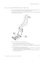
Since the RESET_N signal is shared between Channel A and B of DRAM, there is only one clock
connector (J6) on the W6602A interposer for the RESET_N signal. Therefore, only one channel
has access to the RESET_N at a time. To allow a channel to access the RESET_N, you need to
connect the appropriate flying lead of U4207A to J6.
To use this clock connector for Channel A of DRAM, connect the violet flying lead of the U4207A
cable (connected to J2) to the J6 connector on interposer.
To use this clock connector for Channel B of DRAM, connect the orange flying lead of the
U4207A cable (connected to J2) to the J6 connector on interposer.
If you are using two separate modules to capture Channel A and Channel B simultaneously, and
need to include RESET in your trigger, then connect RESET to one of the channels and use the
ability to arm one module from another from the trigger menus of the two individual modules.
Summary of Contents for LPDDR4
Page 1: ...Keysight W6600A Series LPDDR4 BGA Interposers Installation Guide ...
Page 4: ...4 Keysight W6600A series LPDDR4 BGA Interposers Installation Guide ...
Page 8: ...8 Keysight W6600A series LPDDR4 BGA Interposers Installation Guide Contents ...
Page 10: ...1 Introduction 10 Keysight W6600A series LPDDR4 BGA Interposers Installation Guide ...
Page 78: ...Index 78 Keysight W6600A series LPDDR4 BGA Interposers Installation Guide ...
Page 79: ...Keysight W6600A series LPDDR4 BGA Interposers Installation Guide 79 ...


