


Keysight W6600A-series LPDDR4 BGA Interposers Installation Guide
41
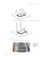
Setting up the W4641A Interposer
5
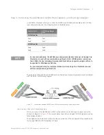
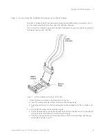
To attach a U4208A or a U4209A ZIF connector to a flex wing of the W6601A interposer, perform the
following three steps.
1 Angle the flex wing of the interposer into the probe cable’s ZIF connector.
2 Align the probe cable’s ZIF connector tabs with interposer’s wing notches.
3 Shut the ZIF door.
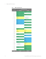
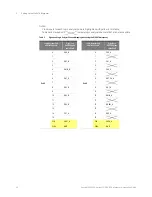
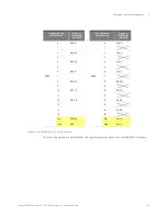
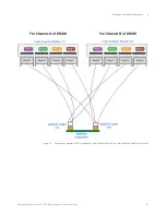
W6601A Interposer Wings Pinout
The table on the next page lists the pinout of the two wings of a W6601A interposer. The table
includes the signals being probed when using the interposer in a dual sampling mode or a quad
sampling mode (supported by the U4164A logic analyzer module).
In this table
,
• Clock/Qualifier inputs are highlighted with yellow
• Signals that can be quad-sampled are highlighted with green
• Single-sampled signals are highlighted with blue
• Table cells marked with
indicate pins that are not accessible.
Summary of Contents for LPDDR4
Page 1: ...Keysight W6600A Series LPDDR4 BGA Interposers Installation Guide ...
Page 4: ...4 Keysight W6600A series LPDDR4 BGA Interposers Installation Guide ...
Page 8: ...8 Keysight W6600A series LPDDR4 BGA Interposers Installation Guide Contents ...
Page 10: ...1 Introduction 10 Keysight W6600A series LPDDR4 BGA Interposers Installation Guide ...
Page 78: ...Index 78 Keysight W6600A series LPDDR4 BGA Interposers Installation Guide ...
Page 79: ...Keysight W6600A series LPDDR4 BGA Interposers Installation Guide 79 ...


