


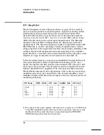


In the DC current function, a current is applied between the
Input I
and
LO
terminals. Ranging is accomplished by relay
K102
and amplifier gain
switching in
U101
. Since a known resistor (the shunt resister) is connected
between these terminals, a voltage proportional to the unknown current
is generated. The voltage sensed at
R121
is measured by the multimeter’s
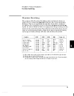
dc circuitry. The table below illustrates the dc current measuring
function configurations.
Resistance measurements are made by applying a known current
through an unknown resistance. The resulting voltage drop across the
unknown resistance is then measured by the multimeter’s dc circuitry.
The 100 M
Ω
range is measured using the known internal 10 M
Ω
resistance (
U102A
) in parallel with the unknown input resistance while
applying the 500 nA current source. The result is computed from the
measured data. The internal 10 M
Ω
resistance is determined whenever
a zero calibration is performed.
In the 2-wire ohms function, the voltage drop is measured across the
Input HI
and
Input LO
terminals. In the 4-wire ohms function, the voltage
is measured across the
HI Sense
and
LO Sense
terminals. Lead resistances
in series with the current source (
Input HI–LO
) are not part of the final
measurement. However, they do reduce the available current source
compliance voltage for the resistor under test. The ohms current source
will become non-linear when the compliance voltage limit is exceeded.
The full scale voltage developed across the unknown resistor and the
dc amplifier gain for each resistance range are tabulated below.
DCI Range
Shunt Resistor
U101–10 Input
Amplifier Gain
ADC Input
3A
1A
100 mA
10 mA
0.1
Ω
0.1
Ω
5.1
Ω
5.1
Ω
300 mV
100 mV
510 mV
51 mV
x10
x100
x10
x100
3V
10V
5.1V
5.1V
Ohms Range
Voltage Across R
Amplifier Gain
ADC Input
100
Ω
1 k
Ω
to 100 k
Ω
1 M
Ω
10 M
Ω
100 M
Ω
100 mV
1 V
5 V
5 V
4.5 V
x100
x10
x1
x1
x1
10 V
10 V
5 V
5 V
4.5 V
5
Chapter 5 Theory of Operation
DC Amplifier
97
Summary of Contents for 34401A
Page 1: ...Keysight 34401A 6 Digit Multimeter Service Guide ...
Page 2: ......
Page 17: ...Contents 10 ...
Page 18: ...1 Specifications 1 ...
Page 33: ...26 ...
Page 34: ...2 Quick Start 2 ...
Page 54: ...3 Menu Tutorial 3 ...
Page 65: ...58 ...
Page 66: ...4 Calibration Procedures 4 ...
Page 98: ...5 Theory of Operation 5 ...
Page 115: ...108 ...
Page 116: ...6 Service 6 ...
Page 132: ...7 Replaceable Parts 7 ...
Page 143: ...136 ...
Page 144: ...8 Backdating 8 ...
Page 149: ...9 Schematics 9 ...


