OPERATION MANUAL
RK-2006SPGM
Pellet fuel burner fitted boiler temperature controller.
Version 5701
+MZL
Page 1: ...OPERATION MANUAL RK 2006SPGM Pellet fuel burner fitted boiler temperature controller Version 5701 MZL ...
Page 2: ... work 15 Alarms cancellation 15 Setting the parameters service mode 15 Table 3 Table service parameter 16 Language selection 18 Brightness saturation contrast of the display 18 Service settings 18 Testing out 18 Fan operation parameters 18 Fuel auger operation parameters 21 Stoker work mode 22 Auger ignition test 23 Ignitor working parameters 24 Cleaning mechanism 26 Central heating pump work para...
Page 3: ... locations that shall be dry Figure 2 presents the electrical con nection diagram For connection of stoker alarm indicator and ash removal system the additional module UM 1 shall be applied CAUTION Before plugging in the controller first check if the wiring system is properly grounded and if the terminal screws of the output connector are tightened CAUTION Total power of the fan central heating an...
Page 4: ... of the device is to set the preset boiler temperature In this hands U need to turn the boiler thermostat knob 4 to set the correct value and confirm it with the OK button or press the knob CAUTION If you enter the room thermostat works in adaptive mode you try to change the set temperature of the boiler may end in failure ie After approval of the new value of the controller can automatically chan...
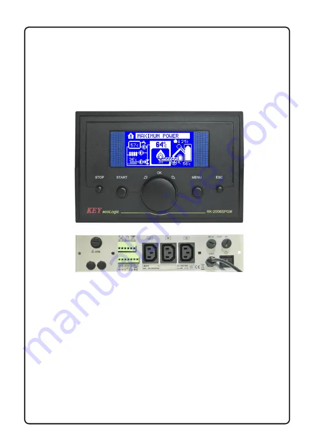
Page 5: ...mp work indicator 9 Burner capacity indicator the higher the capacity the brighter the flame 10 Cleaning device work indicator 11 Stoker work indicator 12 Feeder temperature 13 The operation indicator summer mode 14 The temperature circuit 2 15 The operation indicator circuit pump 2 16 The operation indicator mixing valve 17 Fan 18 Mixing pump work indicator 19 Return water temperature 20 Ignitor ...
Page 6: ... water pumps operation but automatic ignition does not follow AUGER EXTINCT EMERGENCY SHUT DOWN Fuel ignition in auger channel The controller empties ignited fuel from the auger channel until temperature drops ALARMS Safety and temperatures sensors failure alarms STOP Controller maintains central heating and domestic water pumps operation only to protect the boiler against overheating and auger ch...
Page 7: ...r feeding rate is adjusted by the technician Pressing STOP button exceeding time limit for cleaning thermostat contacts opening or if water temperature in domestic water tank is obtained during operation in MAX POWER mode will result in switching of the controller into EXTINCTION SHUT DOWN mode MODULATED POWER OPERATION MODE Depending on desired parameters the controller may gradually reduce fuel ...
Page 8: ...quence Afterburning EXTINCTION CLEANING Automatic burner cleaning occurs after time set limit by programmer In this mode controller starts cleaning system for preset time After this procedure controller resets back to STANDBY mode AUGER MANUAL REFILLING User may activate auger manual refilling function When device is in STOP mode press START and hold button for 5 seconds to start refilling Refilli...
Page 9: ...by the technician Out of fuel alarm will be activated To turn on the controller again first refill fuel cancel the alarm with STOP button and begin setting up process by pressing START button Emergency alarm Depending on construction type the boiler may be equipped with emergency sensor e g hopper cover sensor Activation of the alarm will result in fan and auger turning off and switching the contr...
Page 10: ...r activates the pump absolutely CO The increase in water temperature in the boiler to the value programmed in parameter service TEMPERATURE BOILER OVERHEAT will turn off the fan heating pump switch the controller to STOP mode without starting the process of extinction and trigger the alarm CAUTION This alarm may be cancelled if boiler water temperature drops below the overheating temperature setti...
Page 11: ...r the para meter will be backlit You can change the value of the selected parameter by turning the knob To confirm the change press the knob again and the controller will return to the list of parameters To leave the mode of change and restore the previous va lue of a parameter press the MENU or ESC button If the device is left either in the changing or viewing the parameters mode for 60 seconds r...
Page 12: ...the WOOD fuel is set you can burn the wood in the pellet boiler the controller operates at the wood fuel burning settings WOOD PELLET once the wood has been burned the controller switches to pellet burning and full service to the pellet boiler is provided CAUTION Fuel type may be changed if the controller is in STOP mode only 1 2 Desired boiler temperature it is the temperature setting that will b...
Page 13: ...tivation of program for bacterial flora liquidation in domestic water tank When YES is selected it activates the process of heating the domestic water tank above 75 C When the required temperature is obtained the controller switches off the bacterial flora liquidation program automatically CAUTION Bacterial flora liquidation option shall be switched on in the night or if water intake does not foll...
Page 14: ...f the system is fitted with flame temperature detector parameters change and viewing is unavailab le 1 13 The current furnace brightness determined by an optical detector this parameter displays the current flame brightness measured by the optical detector 1 14 Brightness when fuel ignition has occurred if the optical detector reading will be equal or higher than this desired setting the controlle...
Page 15: ...ancellation The parameter enables the user to cancel the alarms recorded in the controller data storage 1 20 Burner mode INTERMITTENT turning off the thermostat will cause the controller to switch into the POSTCOMBUSTION mode CONSTANT once the thermostat is turned off the controller will switch into the MINIMUM CAPACITY mode instead of the POSTCOMBUSTION the mode saving the ignitor 1 21 SUMMER thr...
Page 16: ... of parameters is possible by turning the multifunction knob possible to edit the parameter is highlighted After selecting the desired parameter press the OK button knob and enter the subgroups of a given parameter Select the parameter you want to change and press the knob a parameter is highlighted Turning the knob set the desired value and then press the knob Giving up mode changes and restore t...
Page 17: ...er power 1 100 F 4 6 Fuel feed for min burner power 1 100 F 4 7 Stoker work mode see description 4 8 Stoker work time 1s 99s 4 9 Stoker pause time 1s 99s 4 10 Stoker extra work time 1s 99s 4 11 Stoker emptying time 1s 99s 4 12 Auger ignition test NO YES 4 13 Auger ignition temperature 20 C 99 C 5 x Igniter 5 1 Flame detector type FD 1 PT 1000 CT 1 2 5 2 CorrectionFD 1 0 99 F 5 3 Hysteresis loss of...
Page 18: ...er modulation factor 1 20 F 9 9 The operating mode of the thermostat NORMAL ADAPTIVE WEATHER F 9 10 The time constant adaptation 1min 99min F 9 11 Burner switch off delay 0min 99min F 9 12 Lowering the thermostat 0 C 30 C 10 x Data transmission 10 1 Data link see description OFF MODBUS RTU 10 2 MODBUS device number 1 247 10 3 MODBUS channel capacity 2400 3600 4800 7200 9600 14400 19200 28800 38400...
Page 19: ...troller it is possible to test various output devices This feature is available in service mode only if the adju stment process is stopped ie The regulator before entering the service mode was in STOP mode Selecting output testing allows the control knob to select the outputs on the display Pressing OK allows you to temporarily attach the selected output In order to complete the testing procedures...
Page 20: ...speed during boiler start setting After time expire the controller will increase fan speed up to the selected Max fan speed during boiler start setting 3 5 Fan speed during ignition this parameter describes power of the fan speed during ignition This parameter is unavailable if Fan speed modulation during igni tion was selected 3 6 Fan speed at max power means the fan power when burner of the boil...
Page 21: ... accumulated gases 3 11 Fan scavenge air purging blow time this parameter specifies blow time 3 12 Fan scavenge air purging pause time this parameter specifies pause time during scavenge This setting is unavailable if Fan scavenge air purging setting was not selected 3 13 Fan speed during scavenge air purging this parameter specifies fan po wer during scavenge air purging This setting is unavailab...
Page 22: ...that is fed to the burner during lighter operation The programmed setting specifies feeding time in percent in relation to the time of whole work cycle Selection of 0s setting will switch fuel feeding during operation of the lighter In this case Initial Fuel Dose set ting be shall be programmed as the value over 0s 4 5 Fuel feed for max burner power this parameter specifies fuel dose fed to the bu...
Page 23: ...ned with Stoker extra work time setting 4 8 Stoker work time this parameter specifies operation time of the stoker in who le work cycle This setting is unavailable if the stoker is switched off or in automatic mode 4 9 Stoker pause time this parameter specifies pause time during stoker operation when in work cycle This setting is unavailable if the stoker is switched off or in automatic mode 4 10 ...
Page 24: ... emergency input is not used NO parameter shall be selected in Auger ignition test setting and contacts of X input shall be closed 4 13 Auger ignition temperature this parameter specifies auger temperature when the controller activates auger ignition alarm This parameter is unavailable when NO was selected in Auger ignition test setting 5 x Ignitor working parameters 5 1 Flame detector type FD 1 C...
Page 25: ...ction procedure is started when the temperature drops or the brightness of the flame to the value of 0 5 5 Flame failure detection delay this parameter specifies how long after the launch procedures for the detection of flame failure or brightness temperature must remain below the hysteresis for the regulator to decide that the furnace was extinguished 5 6 Fuel ignition time after igniter and fan ...
Page 26: ...s parameter determines the maximum operating time of stabilization firing This parameter is not available if the parameter STABILIZATION OF FIRING is set to NO 5 12 Smooth stabilization of ignition setting the parameter to YES will cause the stabilization of firing up the controller gradually increases the amount of fuel fed This parameter is not available if the parameter STABILIZATION OF FIRING ...
Page 27: ...leaning means burner shut down and start cleaning mechanism for the time set in parameter Cleaning mechanism work time After turning off the regulator output deducts the time set in parameter Cleaning mechanism retraction time and then goes to normal working cycle COMBI This mode is a combination of modes AUTO CYCLE Working mechanism starts at the end of the firing and stabilization is cyclical sw...
Page 28: ...mode It specifies the time required for the mechanism retraction to the rest position after turning off the control output 6 4 Cleaning mechanism pause time this parameter is available only when the cleaning mechanism is activated CYCLE ROTO or COMBI mode It specifies the time interval between successive repetition of the cleaning cycle 6 5 Opening time cleaning mechanism this parameter is only av...
Page 29: ... AUTO or COMBI mode Specifies how many hours the burner can work without cleaning If the maximum time is reached the cleaning will run even if there was no required number of shut downs 7 x Central heating pump work parameters 7 1 Central heating pump switching on parameters this parameter specifies the method of central heating pump switching on Selection of THERMOSTAT setting means that central ...
Page 30: ...ting will switch domestic water in the circuit purposed for control of the mixing pump In this case return water temperature sensor shall be connected instead of domestic water sensor and the mixing pump instead of charge pump of domestic water tank 8 2 Domestic water heating hysteresis this parameter indicates water temperature drop in the tank in relation to the programmed setting so that charge...
Page 31: ...vation In this case after wor king for the hot water boiler water temperature may be higher than the temperature required to heat the rooms This may result in extinction of the burner due to excee ding the hysteresis top of the boiler This parameter specifies how long is needed to stabilize the system after the hot water tank with priority enabled During the stabili zation controller disable check...
Page 32: ...er works in burner minimum power mode and boiler temperature increase follows by this programmed setting the controller will start burner extinction shut down 9 4 Burner power switching hysteresis when the programmed boiler water temperature is obtained the controller is switched to minimum power work mode This parameter specifies required water temperature drop so that maximum power work mode was...
Page 33: ...rmostat with contact output Contacts of the thermostat is signaled by the appearance of the ther mometer symbol in the index of the thermostat CAUTION The entrance of the room thermostat is active only during WINTER Lights up when the input state is independent of the mode setting 9 9 Mode of operation of the room thermostat this parameter determines the impact of the entry of the room thermostat ...
Page 34: ...ng external conditions we observe frequent overhea ting of the rooms increase the time constant During niedogrzewania value should be reduced 9 11 Burner off delay this parameter determines the time of the burner in minimum power the thermostat contacts open If after the programmed time the thermostat input will not be closed again the torch will be lit and the controller switches to STANDBY Setti...
Page 35: ...e attributed to your controller and to avoid errors when a number of devices are switched to the bus Default value 1 10 3 MODBUS channel capacity selection of the RS 485 transmission speed Default value 38400 10 4 MODBUS frame format allows you to determine the data frame format used in the RS 485 transmission 8N1 8 bits of data no parity bits 1 bit of silence 8E1 8 bits of data even parity bit 1 ...
Page 36: ...SERVICE changing all of the parameters is possible 10 6 Terminal access level defines to what extent access can be obtained through the remote terminal NO no access through the remote terminal READ OUT terminal allows you to view the parameters and controller work only USER it is possible to change the parameters user s settings default settings SERVICE full access to the controller and viewing al...
Page 37: ...cycle in depending on the characteristics of the weather and room tempera ture AUTO the pump runs continuously The mixing valve keeps the temperature of the second circuit only depending on the characteristics of the weather Mode switching circuit 2 when working in the system only the pump TERM thermostat controls the operation of the pump AUTO Continuous pump operation 13 3 Weather control This f...
Page 38: ...is the minimum boiler temperature that will be set on the boiler 13 7 The hysteresis circuit 2 parameter determines how much the temperature must fall the second circuit to control heat attached 13 8 The minimum temperature circuit 2 The minimum temperature is maintai ned at a second circuit 13 9 Maximum temperature circuit 2 The maximum temperature that can be reach the second circuit 13 10 The t...
Page 39: ...th an external temperature sensor this parameter allows you to specify whether the sensor is installed In the absence of this parameter the sensor has to be turned off 14 2 Point 0 heating curve temperature resulting from the heating curve at an external temperature of 0 C This affects the slope of the curve 14 3 Moving the curve value added to the resulting temperature curve At 0 C outside the he...
Page 40: ...the controller 8 Technical Data Power Supply 230 V 10 50 Hz Power consumption without fan and pump 2 VA Temperature measurement range KTY 81 210 39 109 C 1 C Temperature measurement range PT 1000 30 500 C 3 C Boiler temperature adjustment range 30 90 C 1 C Boiler programmed overheating protection 90 99 C 1 C Boiler equipment overheating protection 95 C 1 C Total outputs rating max 2 A 230 V Dimens...
Page 41: ...41 Figure 2 RK 2006SPGM MZL Controller connection diagram ...
Page 42: ...42 Figure 2 RK 2006SPGM MZL Controller connection diagram ...
Page 43: ...1000 4 11 2005 U PN EN 60730 1 2002 A1 2006 U A12 2004 A13 2005 PN EN 60730 1 2005 A14 2006 PN EN 60730 2 9 2006 PN EN 61000 3 2 2006 U PN EN 61000 3 3 1997 A1 2005 A2 2006 IS1 2006 Information on disposal This appliance is marked according to the European Directive 2002 96 EC on Waste Electrical and Electronic Equipment WEEE The symbol on the product or the documents accompanying the product indi...
Page 44: ...Manufacturer P W KEY 11 200 Bartoszyce ul Bohaterów Warszawy 67 tel 89 763 50 50 fax 89 763 50 51 www pwkey pl e mail pwkey onet pl ...