


Page 6
Page 7
Quick Setup Guide
Initial Setup & Operation for HDMI via Front Panel
The KD-HDMS8x8 is set by default to HDMI Input. To change these default settings please see
“Initial Setup & Operation via CAT6/STP Baluns” section below.
1.
Insert HDMI cables into card slots 1 through 16
»
Slots 1-8 are labeled Rx, and are Input Card Slots 1-8.
»
Slots 9-16 are labeled Tx, and are Output Card Slots 1-8.
»
Connect your source components to the Input cards
»
Connect your displays to the Output cards
»
Power up all sources and displays
2.
Establish an HDMI Handshake for Each Source
»
Push the left selector to access the Main Menu choices
»
Using the left selector, scroll to the “7-EDID Setup” Menu
»
Press the right selector to navigate to the EDID sub-menus
»
With the left selector, scroll to the Input source you wish to copy the EDID to
»
Using the right selector, scroll to the HDMI or CAT6/STP Output you wish to establish an
HDMI handshake for, or select a Default EDID 01-08 from the EDID library (see pg.10)
»
Press the right selector to set the Handshake for that combination
»
Continue this procedure for all Inputs
»
The EDID control and HDMI input set up is stored in a non-volatile memory back up and is
only required during initial set up or when a new display or source is added to the system.
»
Establish a default handshake for ALL Inputs:
»
Using the ‘7-EDID Setup’ Menu, select ‘ALL Inputs’ and scroll to the Output number
you wish to copy the EDID from (HDMI, CAT6/STP or a Default EDID setting) and press
the right selector
3.
Switching via Front Panel
»
Push the left selector to access the Main Menu choices
»
Using the left selector, scroll to the “1-Video Switch” Menu
»
Press the right selector to navigate to the Video Switch sub-menus
»
Using the left selector, scroll to the Output you wish to select
»
Using the right selector, scroll to the Input you wish to select
»
Finally, press the right selector to make the switch
4.
Sending your output via KD-BBRX CAT6/STP Receive Balun(s)
»
Both HDMI and CAT6/STP Outputs are active on all Output Card Slots, therefore no
configuration is necessary to activate the CAT6/STP Output for each Tx Card Slot.
5.
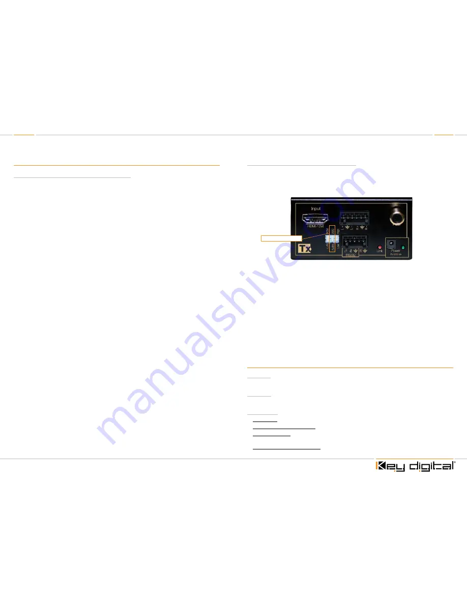
Sending your source via KD-BBTX CAT6/STP Transmit Balun(s)
»
Set dipswitch #2 of the KD-BBTX Balun to “DDC” in order to establish a proper HDMI
handshake
»
Configure the appropriate Input Card Slot to activate its CAT6/STP input using the
“6-Video Input Setup”
Initial Setup & Operation via CAT6/STP Baluns
When using Key Digital Baluns (RX/TX) you must use the following procedure to correctly format
both the baluns and HDMS8x8 matrix switcher for correct operation.
»
NOTE: Slots 1-8 are inputs, slots 9-16 are outputs.
»
The KD-BBTX Dipswitch #2
MUST
be set to the DDC position.
½
IMPORTANT: Make sure that you power up all baluns, sources and displays.
Confirm that you have an active connection on the Balun indicated by the solid
red “LINK” LED.
1.
By default, the KD-HDMS8x8 is configured to accept a direct HDMI connection. When using a
KD-BBTX, you MUST change the input mode from HDMI to CAT6/STP to enable the switcher
to “see” the CAT6/STP/Balun input. Select “6-Video Input Setup” from the main menu. Press
the right selector to navigate to the sub-menus. Using the left selector, scroll to the Input
number you wish to change. Using the right selector, scroll to select “CAT6/STP” and press the
right selector to enter your choice.
2.
Repeat procedure for any other input where a KD-BBTX is being used.
3.
Once you have correctly configured the inputs to accept either HDMI and/or CAT6/STP/Balun,
you need to establish the correct HDMI “handshake”.
4.
See previous section on establishing an HDMI handshake.
Front Panel Menu Selection Controls:
Power On
½
The unit will power up with a push on either the left or right Selector.
Power Off
½
The unit will power off through IR, Remote, RS-232 or TCP/IP commands only.
Left Selector
½
Main Menu: To access the Main Menu push this selector once.
½
To Select Main Menu Options: Turn selector left or right to select Menu Options 1-9
½
Sub-Menu values: Turn this selector to scroll through the sub-menu selections. There will be left
and right sub-menu choices. Use the left selector to change left side options
½
To Go-Back to a previous menu: from whatever menu you are presently in you may return to the
previous menu by pressing this selector once. You will return to the menu you were previously in.
Dispwitch # - Select DDC


