background image

Page

Page

Additional Installation Tips

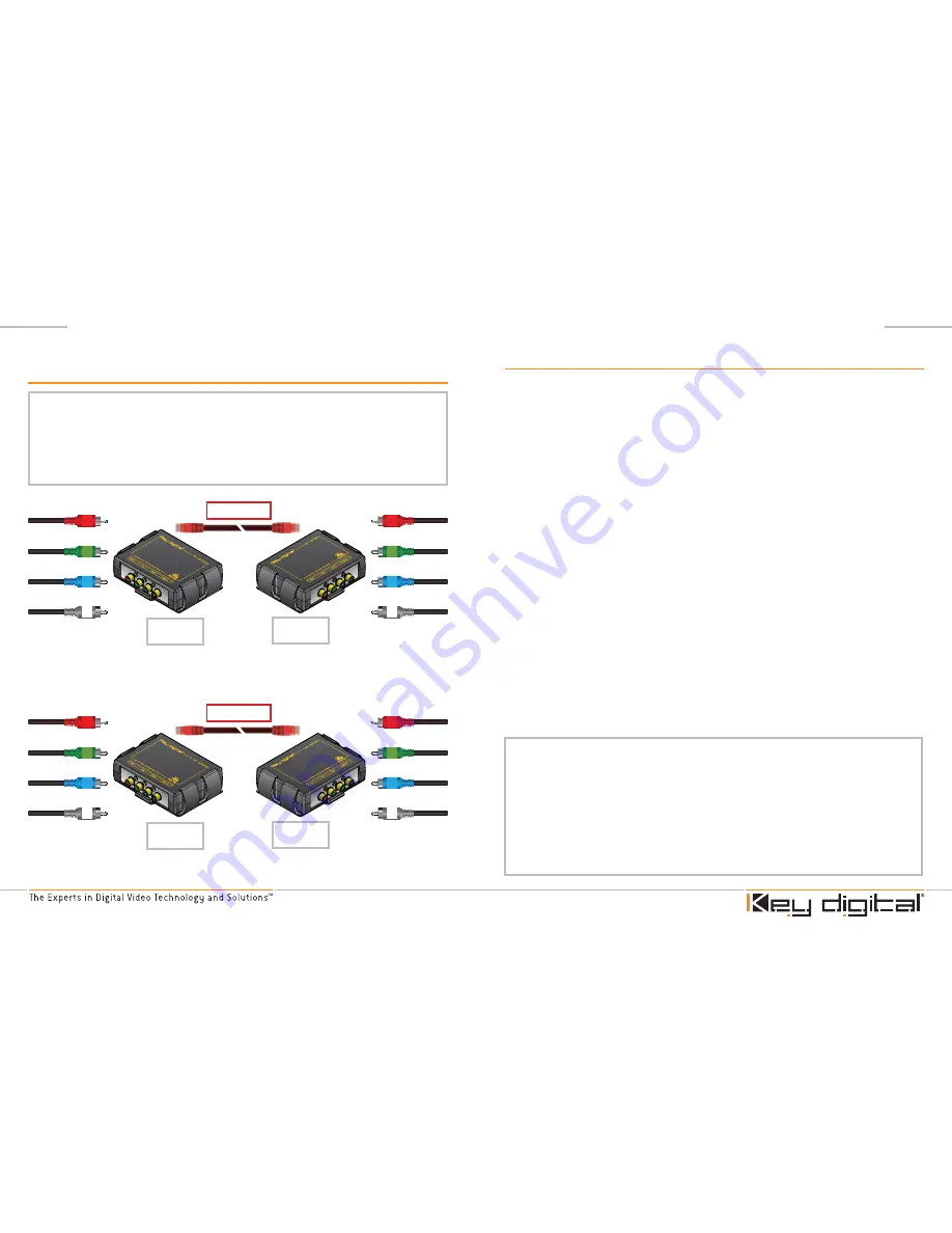
Example Two – Four BobCAT Setup to support RGB with Multi-Channel Analog 
Audio

In this case, we can use two BobCAT units to transmit Component Video (RGB) signals 
in addition to multi-channel (L, C, R, LS, RS) analog audio.  
To do so:

Connect Component Video cables to the corresponding ports labeled “R,G, and B” 
on the first transmitting BobCAT.
Connect left analog audio signal to the port labeled “PCM” on the first transmitting 
BobCAT.
Connect the center, right, LS, and RS analog audio signals to the ports labeled  
“R, G, B, and PCM”, respectively, on the second transmitting BobCAT.

Use two additional BobCAT units to receive the two CAT 5 cables from the transmitting 
units above.  Take care to connect output cables (RGB and L, C, R, LS, and RS) to the 
ports that correspond to those used for input on the transmitting BobCAT.

1.

2.

3.

*Note that these are just two examples of the many different possible configurations.   
If you keep in mind that inputs and outputs should be one-to-one (that is, the signal 
feeding a specified port on the transmitting BobCAT can be output on the corresponding 
port on the receiving BobCAT) then there are many uses for multiple BobCAT setups with 
the formats mentioned above.
Additionally, the BobCAT units DIP switches connect shield to common ground when set 
to “On”.  Switch “1” is for “R” port, switch “2” is for “G” port, switch “3” is for “B” port, and 
switch “4” is for “PCM” port.  Connecting shield to common ground can help eliminate 
visible “noise” on the video signal.  See “Troubleshooting” section of this manual.

Component (YPrPb) Video with 5-Channel Surround Application Example 

(Four Box Setup)

ANY input on BobCAT can be used for any of the following video/ audio signals.  
As long as you use the same output on the termination unit.  Y,Pr,Pb,R,G,B,H,V, S-Video 
(with break-out cable), Composite Video (CV), Left Front Audio, Right Front Audio, Center 
Speaker, Subwoofer, Left Rear Audio, Right Rear audio (Any Audio configurations from 2.0 
– 7.1 and beyond). In some cases this requires a “multi-box” application.

Y

Pr

Pb

L

C

R

LS

RS

Box 1 Tx

Box 1 Rx

Box 2 Tx

Box 2 Rx

CAT5/6 Cable

CAT5/6 Cable

C

R

LS

RS

Y

Pr

Pb

L

Summary of Contents for KD-C5CWP

Page 1: ...digital video pioneer Mike Tsinberg develops and manufactures high quality cutting edge technology solutions for virtually all applications where high quality video imaging is important Key Digital is at the forefront of the video industry for Home Theater Retailers Custom Installers System Integrators Broadcasters Manufacturers and Consumers We provide total video system solutions because we know...

Page 2: ...XBNC KD C5CWP CAT5 6 Cable Please read all instructions to insure safe operation of the product Table of Contents Dolby 7 1 Audio Application Example 2 Installation Instructions 3 RGBHV Video plus L R Audio Application Example 4 Additional Installation Tips 5 Component YPrRb Video with 5 Channel Surround Application Example 6 RJ45 CAT5 Cable Pinout 8 Cable Distance and Supporting Resolution 8 Disp...

Page 3: ...ding standard Left Right digital audio and Dolby Digital encoded bit streams If you are not running audio with video through the BobCAT simply leave this port disconnected 4 Connect one end of your CAT 5 cable to the CAT 5 port of the BobCAT intended as the transmitting device and the other end of your CAT 5 cable to the CAT 5 port of the BobCAT intended as the receiving device Use standard CAT 5 ...

Page 4: ...G and B on the first transmitting BobCAT Connect H sync cable to the port labeled PCM on the first transmitting BobCAT Connect V Sync cable to the port labeled PCM on the second transmitting BobCAT Connect left analog audio signal to the port labeled R on the second transmitting BobCAT Connect right analog audio signal to the port labeled G on the second transmitting BobCAT Use two additional BobC...

Page 5: ...uts and outputs should be one to one that is the signal feeding a specified port on the transmitting BobCAT can be output on the corresponding port on the receiving BobCAT then there are many uses for multiple BobCAT setups with the formats mentioned above Additionally the BobCAT units DIP switches connect shield to common ground when set to On Switch 1 is for R port switch 2 is for G port switch ...

Page 6: ...AT5 Cable Length 480i 480p 576i 576p 720p 1080i 300 500 700 Troubleshooting Problem Solution Display has visible lines and or colors appear incorrectly A device or cable in the system may not be properly grounded Replace Component cables Also set DIP switch settings on the BobCAT individually to on off positions These switches connect on disconnect off cabling to common ground Display drops in out...

Page 7: ...accordance with the manufacturer s instructions Do not install near any heat sources such as radiators heat registers stoves or other apparatus including amplifiers that produce heat Only use attachments accessories specified by the manufacturer Refer all servicing to qualified service personnel Servicing is required when the apparatus has been damaged in any way such as power supply cord or plug ...

Page 8: ...it may break Warranty All Key Digital products are built to high manufacturing standards and should provide years of trouble free operation They are backed by a limited two year parts and labor warranty 1 2 3 1 2 3 Important Product Warnings Distances for CAT5 are suggestive and depend on the following factors How to Contact Key Digital Repairs and Warranty Service Should your product require warr...

Reviews: