4 - PRODUCT INSTALLATION
4.1 - Installation
Before proceeding with the installation, check the integrity of the
product and that all components are present in the package.
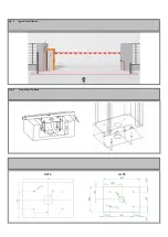
1. Provide a foundation pit and arrange one or more conduits for the
passage of the electrical cabling (Fig. 3).
2. Assemble the 4 anchoring brackets on the mounting plate and
fasten with the 4 bolts provided.
3. Pour the concrete into the inside of the pit and position the base
plate.
NOTE: verify that the plate is perfectly leveled and parallel to the
opening barrier.
4. Wait for the complete setting of the concrete.
5. Unscrew the 4 nuts that hold the base joined to the anchoring
brackets and position the rack on the plate (Fig. 4).
6. Attach the bar to the barrier body.
ATTENTION: never move the barrier rod for any reason until it
is horizontal, and do not perform the emergency or manual ma-
noeuvre if the rod is not installed.
4.2 - Unlocking the bar
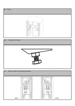
If you need to perform manual actions on the barrier rod, proceed as
follows (Fig. 5):
- Cut the power supply.
- Insert the release key provided and remove the latch, insert the allen
wrench and turn it 90°.
- In this way you can detach the internal reduction system to allow the
4.3 - Adjustment of rod angle
If you need to adjust the stops of the rods, proceed as follows (Fig. 6):
- Loosen the locking nut (located on the box for ALT4 or on the rocker
arm for ALT6).
- Adjust the screw to the desired height.
emergency manoeuvre.
- Perform the manual manoeuvre.
- To engage the transmission again, turn the allen wrench back to its
original position and close the lock.
- You can now restore the power supply and check that everything is
working correctly.
- Fasten the locking nut back in place.
4.4 - Changing the direction of opening
ALT4 VERSION
- Turn off the power supply and, with the manual manoeuvre, place
the rod vertical, restore the transmission and remove the rod to pre-
vent hazardous conditions.
- Open the door, loosen the tension system of the spring and then
release it from the upper fastening.
- Remove the fastening screw so as to free the spring in the upper
part and allow it to be positioned on the opposite side of the fastening
lever.
ALT6 VERSION
- Turn off the power supply and, with the manual manoeuvre, place
the rod vertical, restore the transmission and remove the rod to pre-
vent hazardous conditions.
- Open the door, loosen the tension system of the springs and then
release the springs from the upper fastening.
- Remove the fastening screws so as to free the springs in the upper
part and allow them to be positioned on the opposite side of the fa-
stening lever.
- Unscrew the lever so as to allow it to rotate and allow fastening of
the springs in the opposite position.
- Fasten all in the indicated positions and tension the springs (see the
paragraph on balancing).
4.5 - Balancing
- Cut the power supply.
- Release the rod.
- Position the rod at about 45°.
- Loosen the locking nut(s) of the spring tensioner(s).
If the rod tends to fall, adjust the spring tensioner(s) so that it is
stopped.
- When balancing is complete, fasten the locking nut(s) again.
- Restore motorized operation by turning the release key in the op-
posite direction.
- Restore the power supply and check that everything works correctly.


