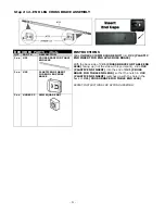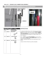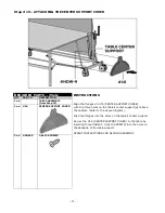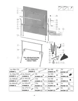
Step #4 – CENTER SUPPORT ASSEMBLY – LOCKING WHEEL
-
13
-
REQUIRED PARTS – 2 Sets
INSTRUCTIONS
QTY PART #
DESCRIPTION
1 ea
CENTER SUPPORT ASSEMBLY
(From Step 3)
2 ea #35
WHEEL FOR LOCKING CASTER
1ea #HDW-5 M8X110
BOLT
4 ea #HDW-12
16 MM WASHER
1 ea #HDW-15
M8 BOLT CAP
Slide #HDW-5 (M8x110 BOLT) though #HDW-12
(16MM WASHER), then though #35 (WHEEL FOR
LOCKING CASTER), then though another #HDW-12
(16MM WASHER).
Place CENTER SUPPORT ASSEMBLY from Step 3
with the flange facing away. (Please refer to diagram
above.)
Slide the bolt assembly with the washers and wheel,
through the LOCKING WHEEL PIVOT that is attached
to the right hand side of the base of the CENTER
SUPPORT ASSEMBLY.
Slide a #HDW-12 (16MM WASHER), the #35
(WHEEL FOR LOCKING CASTER), and a #HDW-12
(16MM WASHER) onto the #HDW-5 (M8x110
BOLT).
Place the #HDW-15 (M8 BOLT CAP) to the end of the
#HWD-5 (M8x110 BOLT) and twist to secure the
assembly. Tighten the bolt so that it is secure, and yet
the pivot assembly is able to rotate freely.
REPEAT INSTRUCTIONS FOR SECOND ASSEMBLY.
INSTRUCTIONS FOR LOCKING WHEELS
Press the red wheel lock lever down to lock the wheels
in place.
To release pull up on the red lock.
Summary of Contents for K-7122-490
Page 28: ... 28 ...


