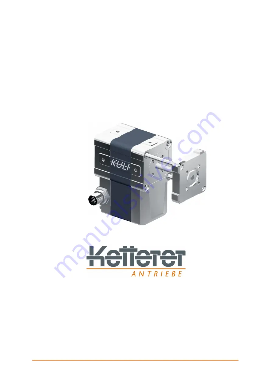
background image

3215.72-01i01 Rev. A 


Assembly instructions 


„KuLi - electric short stroke linear actuator“ 

3215.00-XXXX 


Original assembly instructions for partly completed machines 

According to machinery directive 2006/42/EG  

Attachment VI 

Document No. 3215.72-01i01 

04 / 2022


Summary of Contents for KuLi Series

Page 1: ...bly instructions KuLi electric short stroke linear actuator 3215 00 XXXX Original assembly instructions for partly completed machines According to machinery directive 2006 42 EG Attachment VI Document...

Page 2: ...r de 2022 B Ketterer S hne GmbH Co KG 78120 Furtwangen All rights reserved in particular the right of reproduction distribution and translation No part of this manual may be reproduced in any form or...

Page 3: ...connector positions 11 3 2 2 Available accessories 11 3 3 Technical data operating conditions 12 Technical data operating conditions 12 3 4 Dimensions 15 3 5 General requirements for the master contr...

Page 4: ...2 2 Teach run during operation 31 7 2 3 Teaching the travel range after switching on 32 8 Operation 33 9 Disassembly Shutdown 35 10 Maintenance 37 11 Self help and diagnosis in case of malfunction 38...

Page 5: ...Depending on the version or modification status of the product there may be differences compared to these instructions 1 2 Scope These instructions are valid for the partly incomplete machine with ar...

Page 6: ...is placed in front of activities where several causes can lead to hazards Hot surface warning This warning sign stands in front of activities where there is a hazard from hot surfaces which can lead...

Page 7: ...is warning sign stands in front of activities where an unexpected automatic start up of rotating components can occur Warning of crushing hazard This warning sign stands for activities where hazards e...

Page 8: ...situation which if not avoided will result in death or serious irreversible injury DANGER Indicates a hazardous situation which if not avoided could result in death or serious irreversible injury WARN...

Page 9: ...ific hazard The warning is structured as follows SIGNAL WORD Nature of the hazard and its source Possible Consequence s of disregard Action s to avoid the hazard 1 4 2 Structure of the embedded warnin...

Page 10: ...alth of persons and cause extensive damage to property 2 1 Personnel Qualification und obligations Information All activities on the KuLi may only be carried out by competent and qualified persons The...

Page 11: ...rating and maintenance personnel to report occurring and recognizable safety defects immediately to their superiors During start up and operation the operator must ensure that there are no persons in...

Page 12: ...e operating conditions specified in this document chapter 3 3 Technical data Operating conditions The KuLi may only be operated in one of the three operating modes If operation outside of these modes...

Page 13: ...i is switched off Only allow work on the electrical supply to be carried out by qualified electrical personnel Make sure that all phases and the complete electrical system are voltage free There must...

Page 14: ...pneumatic cylinders for example With a housing length of 68 mm the KuLi performs a stroke of 40 mm The push pull forces are up to 300 N Maximum speed in load free condition is 445 mm s Parameters are...

Page 15: ...are possible 3 2 2 Available accessories Connect Box part number 3215 49 01 The KuLi Connect Box parameterization adapter is designed to transfer programming from the PC to the KuLi and in combination...

Page 16: ...without connector Length 81 8 mm Width 49 mm Height 90 mm Weight 0 9 kg Material of the housing Zinc die casting ZP5 aluminium Stroke length Max stroke 40 mm Spindle pitch 6 mm Max Push Pull force dyn...

Page 17: ...50N increments using the parameterization software via PC see Chapter 7 1 The Expert Mode software variant EX KuLi BX VS X EX X X offers a maximum of adaptation options to your application Individual...

Page 18: ...Product description 3215 72 01i01 Rev A P a g e 14 The lifetime may vary depending on operating and installation conditions and is load dependent See following figure...

Page 19: ...Product description 3215 72 01i01 Rev A P a g e 15 3 4 Dimensions The dimensions of the KuLi for all possible connector positions are shown below...

Page 20: ...ust have the following functionalities I O control The KuLi short stroke linear actuator can be connected to the control system using a simple M12 cable In I O mode the actuator is controlled via the...

Page 21: ...the temperature ranges 15 C to 70 C during transport 4 2 Unpacking When removing the packaging pay attention to the danger of cutting cardboard boxes Do not use sharp objects for unpacking Make sure t...

Page 22: ...ve gloves CAUTION Danger due to crushing and impact points When assembling the KuLi crushing and impact points may occur in the area of the push rod guide This may result in injuries Wear your persona...

Page 23: ...eves shown in green are not included in the scope of delivery Note The KuLi also has additional holes on the side and top which can be used for mounting Be sure to observe the smaller diameter of M4 a...

Page 24: ...es CAUTION Risk of damage to the KuLi due to the effect of radial forces The effect of radial forces may cause the KuLi to break This may result in damage to the corresponding application When connect...

Page 25: ...embly WARNING The KuLi performs a reference run when the supply voltage is applied This results in the risk of crushing in the travel range The assembly may only be carried out in a voltage free state...

Page 26: ...ent safety features to adequately reduce the risk of unexpected start up Observe the reference run when applying the supply voltage WARNING Danger due to uncontrolled movements During start up uncontr...

Page 27: ...touch the KuLi for start up when it is no moving CAUTION Danger from hot surfaces Surfaces of the KuLi may be hot during operation and cause burns Touching the components of the KuLi during start up...

Page 28: ...this can be done in 50N steps using the parameterization software via computer see chapter 7 Reference run after switching on After switching on the Kuli must perform a reference run This is initiated...

Page 29: ...terer After parameterization start up must also be carried out in cooperation with Ketterer Qualification of the personnel Connect Box The installation and electrical connection of the device may only...

Page 30: ...connection Type B The Connect Box is linked via the connection cables with 5 pin M12 plugs Pin assignment see Chap 5 2 1 Disconnect the connection cable 1 to the PLC at the KuLi and connect it to the...

Page 31: ...oved by the KuLi can be set via the software There are various options for this Button TEACHING The KuLi moves with reduced force to the inner position the outer position and then back to the inner po...

Page 32: ...checked under real conditions If the CHECK button is pressed the Kuli moves to the other end position in each case The movement distance and the movement speed are measured and displayed If necessary...

Page 33: ...move to the end position For this purpose new movement commands are periodically generated by the KuLi until the end position is reached or the control changes the end position Hold position With thi...

Page 34: ...e end position corresponding to the control signal After the fourth pulse which is longer than 100 ms the Kuli activates both outputs The Kuli is now ready for reference run This starts as soon as the...

Page 35: ...ce point Each time the input signal at the control input changes a new position is approached and taught Control input Action Output 1 Output 2 6 Pulse Activate teach mode 24V 24V 24 0V Move to refere...

Page 36: ...s Activate teach mode 24 V 24 V 24 V 0 V Move to reference point 24 V 0 V 0 V 24 V Move to outer end point 0 V 24 V 24 V 0 V Move to inner end position 24 V 0 V When an end position is reached the res...

Page 37: ...d start up A mains disconnecting device according to EN60204 1 2019 Chapter 5 4 shall be provided by the integrator Do not reach into the KuLi during operation WARNING Danger due to uncontrolled movem...

Page 38: ...with the KuLi is permitted during operation WARNING Danger from being pulled in caught grasped and crushed The stroke movement of the KuLi can cause objects items of clothing or body parts to be pull...

Page 39: ...ee condition of all components is ensured Observe the 5 safety rules Wait at least 5 minutes after ensuring that no voltage is present before starting disassembly work This ensures that there is no re...

Page 40: ...zed restarting e g by using a key lock on the mains disconnection device information sign Only access the KuLi after you have disconnected the power supply Preparatory activities for disassembly shutd...

Page 41: ...horized restarting e g by using a key lock on the mains disconnection device information sign Only access the KuLi after you have disconnected the power supply CAUTION Danger due to sharp edges on par...

Page 42: ...on torque Every 6 months Torque depends on the used screw Tight fit of the screwed connection cables Every 6 months Hand tighten Lubrication No action necessary All motor components are lifetime lubr...

Page 43: ...g materials is subject to the local disposal regulations and the environmental protection laws in the country of use 13 Repair In case of service or repair contact B Ketterer S hne GmbH Co KG Bahnhofs...

Page 44: ......

Reviews: