K4C COMPACT-MULTI – INSTALLATION/OPERATION MANUAL
K4C Compact-multi
Feb
-06
11
6.0 OIL TANKS & PIPING
Tank installation must conform to local requirements.
Install according to the applicable code. Minimize number of connections in suction line
and make all connections as tight as possible. Use a pipe joint compound suitable for
oil on all pipe threads. To reduce possibility of air leaks, tighten stem packing gland nut
on any valves installed in the suction line. Also, be sure the oil filter is tight, as filter
gaskets often shrink. Check for kinks in the oil lines as well as for possible air pockets
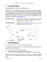
and for loose connections. Two filters as shown below are recommended. Further
information is available at
www.kerrheating.com
.
ONE PIPE SYSTEM
Where the tank is above the burner and when the oil flows
by gravity to the oil pump, a single-stage fuel unit with a
single oil line to the pump may be used.
TWO PIPE SYSTEM
When single line is unsuitable, use double line or see your
KERR dealer for special oil line fittings.
7.0 BLOWER REMOVAL
Use a reversing drill with 1/4” hex drive for the sheet metal screws.
The KERR K4C Compact-multi has a quick release blower suspension system that is
designed to be tight and rattle free.
a.
Remove front panel to blower compartment.
b.
Remove the screw (s) from the blower key. (Figure -2A)
c.
Remove the blower key and slide the blower towards the burner. (Figure -2B).
Replace the blower assembly using the reverse procedure. See diagram.
DO NOT
start the oil burner until installation is complete and all cleanout covers are secured in
place.


