TECHNICAL
DATA
SHEET
T.D.S.
NO.
4.2
PCN:
______
Supercedes
PCN:
_____
Date
03
‐
10
‐
06
4.1.1
Remove
the
wiper
box
seals
and
cap/plug
the
seal
opening.
4.1.2
Clean
the
pump
outer
surfaces
prior
to
painting.
4.1.3
If
painting
is
required
mask
crank
and
lubricator
shaft
surfaces
and
keyways.
If
painting
does
not
apply,
go
to
Para.
4.1.8.
4.1.4
Paint
as
specified
by
the
customer
order
or
as
required.
4.1.5
Apply
a
thin
layer
of
grease
to
the
exposed
oil
seal
lips.
4.1.6
Apply
a
thin
layer
of
heavy
rust
preventative
to
the
exposed
crank
and
lubricator
shaft
surfaces
and
keyways.
4.1.7
Wrap
the
exposed
crank
and
lubricator
shafts
with
waxed
tape.
4.1.8
Carefully
wrap
the
following
parts
prior
to
placing
them
into
polyurethane
bags.
Oil
level
gages,
lube
pressure
gages,
and
breather
caps.
4.1.9
Finish
box,
crate
and
mark
the
parts
from
Para.
4.1.2
after
final
inspection
(see
Para.
4.2.2).
4.2
Shipping/Receiving
(New
Pumps
Only)
4.2.1
All
pumps
and
accessories
(as
applicable)
will
be
final
inspected
by
Kerr
Pump
personnel
prior
to
shipping.
Any
witnessed
or
third
party
inspection
will
be
signed
‐
off
by
the
purchaser
or
customer
representative
prior
to
final
crating
and
shipment.
4.2.2
Export
crating
will
be
performed
by
either
an
approved
Kerr
Pump
source
or
as
specified
by
the
purchaser
or
customer.
Any
third
party
inspection
will
be
coordinated
with
the
source.
4.2.3
Upon
receipt
of
the
shipment,
the
purchaser
or
customer
is
responsible
for
inspection
and
repair
of
damaged
coatings
at
the
expense
of
the
shipper.
5.0
WARRANTY/START
‐
UP
5.1
Pumps
prepared
per
the
above
procedure
qualify
for
the
“Standard
Terms
&
Conditions”
in
force
on
the
date
of
shipment.
5.2
If
the
pump
storage
period
is
less
than
6
months,
follow
the
Short
Term
Pump
Preparation
Procedure.
5.3
Prior
to
start
‐
up:
5.3.1
Remove
all
storage
caps,
plugs,
and
covers.
5.3.2
Replace
any
damaged
or
cracked
O
‐
rings
or
gaskets.
5.3.3
Inspect
power
end
shaft
oil
seals
and
replace
if
cracked,
split
or
damaged.
5.3.4
Install
crankcase
drain
plug,
lubrication
level
site
glass
and
breather
cap.
5.3.5
Install,
if
applicable,
any
oil
pressure
and/or
temperature
gage.
5.3.6
Check
the
connection
of
the
plunger
and
pony
rod
to
the
crosshead
prior
to,
and
after,
initial
run
‐
in
of
the
pump.
5.3.7
Fill
the
crankcase
to
the
proper
level
with
the
specified
lubricant.
Summary of Contents for KT-3350XP
Page 19: ......
Page 22: ......
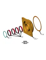
Page 24: ...KA 26G KA 28S GLAND GASKET KA 26 PONY ROD KA 28 SEALS KA 26 A PONY ROD PACKING GLAND ASSEMBLY...
Page 26: ......


