background image

24

 EN

Preparing for playback

SETUP

ON/STANDBY    

POWER ON/STANDBY    

MULTI CONTROL 

%

/

/

@

/

#

Setup

POWER RCVR

RCV Mode

Multi 

%

/

/

@

/

#

ENTER

Enter

Speaker settings

To enable you to obtain optimum enjoyment from the receiver’s listening

modes, make sure to complete the speaker settings (subwoofer, front,

center, surround and surround back speakers) as described below.

1

Turn on the power to this receiver by pressing the POWER ON/
STANDBY   (For U.S.A. and Canada) or ON/STANDBY   (For
Europe and Australia) key (or POWER RCVR key).

2

If you want to use the remote control unit, press the RCV Mode
key on the remote to set it to the receiver control mode.

3

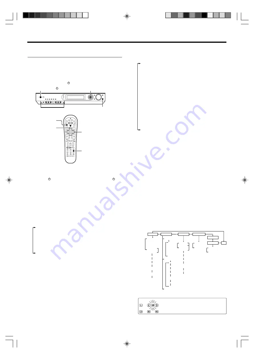
Initiate the setup mode.

1

Press the SETUP key (or the Setup key).

2

Use the MULTI CONTROL 

@

 / 

#

 (or the Multi 

@

 / 

#

 keys)

for the following displays.

1

"

SP SETUP

"

2

"

SP LEVEL

"

3

"

DISTANCE

"

4

"

ASSIGN.

"

5

"

LFE LEVEL

"

6

"

GAME FUNC

"

7

"

EXIT

"

÷

While the main setup screen is displayed, the setup mode

can be canceled by pressing the 

SETUP

 key (or the 

Setup

key) or selecting "

EXIT

" and then pressing the 

ENTER

 (or the

Enter

 key).

4

Select the setup method.

1

Select "SP SETUP" and press the ENTER key (or the
Enter key) to select the speaker setup method.

2

Use the MULTI CONTROL 

@

 / 

#

 (or the Multi 

@

 / 

#

 keys)

for the following displays.

1

"

HTB1 6.1CH

"

Select "

HTB1 6.1CH

" if you use speaker

system KS-3100EX. 

*

2

"

HTB1 5.1CH

"

Select "

HTB1 5.1CH

" if you use speaker

system KS-2100HT. 

*

3

"

HTB2 6.1CH

"

Select "

HTB2 6.1CH

" if you use speaker

system KS-708HT+KS-308EX or KS-308HT+KS-308EX. 

*

4

"

HTB2 5.1CH

"

Select "

HTB2 5.1CH

" if you use speaker

system KS-708HT or KS-308HT. 

*

5

"

HTB3 6.1CH

"

Select "

HTB3 6.1CH

" if you use speaker

system KS-908EX. 

*

6

"

HTB3 5.1CH

"

Select "

HTB3 5.1CH

" if you use speaker

system KS-908HT.

*

7

"

CUSTOM

"

Select to set up the speakers according to

the speaker system in use. (Speaker setup is required

every time after the speaker system is changed.)

8

"

EXIT

"

Press the 

ENTER

 (or the 

Enter

 key) again to

return to the main setup displays.

*

Model availability may differ depending on the country

and sales area.

÷

When the 5.1 channel speaker system configuration is used

or the speaker setting is set to "

BS/SW OFF

", the PL 

II

x, DTS-

ES and DOLBY EX listen modes cannot be selected.

If you selected "HTB1 6.1CH", "HTB1 5.1CH", "HTB2 6.1CH",

"HTB2 5.1CH", "HTB3 6.1CH" or "HTB3 5.1CH" in the above:

Press 

ENTER 

(or the 

Enter 

key), then press 

MULTI CONTROL

%


/


 (or the  

Multi


%


/


 keys) to select "

OK

", and press 

ENTER

(or the 

Enter 

key) again to establish the setup.

÷

Select "

CANCEL

" to return to the status before setup.

÷

When you use a KENWOOD speaker system and select

"

HTB1 6.1CH

", "

HTB1 5.1CH

", "

HTB2 6.1CH

", "

HTB2 5.1CH

",

"

HTB3 6.1CH

" or "

HTB3 5.1CH

" set the speaker setup, the

audio will be corrected automatically according to the

speaker characteristics.

If you selected "CUSTOM" in the above:

Press 

ENTER

 (or the 

Enter

 key) to proceed to detailed setups.

The flow of the SETUP is as follows;

SP SETUP

SP LEVEL

DISTANCE

ASSIGN.

EXIT

LEF LEVEL

GAME FUNC

Front Left

Center

Front Right

Front Left

Right Surround

Surround  Back

(Right/Left

Surround Back)

Subwoofer

HTB 1 6.1CH
HTB 1 5.1CH
HTB 2 6.1CH
HTB 2 5.1CH
HTB 3 6.1CH
HTB 3 5.1CH

CUSTOM

EXIT

Subwoofer

Front

Center

Surround

Surround

Back

MANUAL/OFF

AUTO

L

C
R

SR

SL

BS

(RB/LB)

SW


L

C

R

SR

BS

(RB/LB)

SL

SW

Digital

EXIT

D4 Video

METERS

EXIT

FEET

MODE 1
MODE 2

OFF

BS/SW 

amp

Subwoofer

Re-mix

EXIT

÷

The subwoofer setting indication "

SUBW

" appears.

s U B W

0 N

Continued to next page

*5462/20-36/EN

04.4.13, 8:01 PM

24

Summary of Contents for VRS-7100

Page 1: ...ontrol it is important to read the operating instructions and obtain a proper understanding of the remote control and how to switch its operation modes etc Using the remote control without completely understanding its design and how to switch the operation modes may result in incorrect operations Quick Start Reference Please read the following pages so that you can enjoy the surround sound at the ...

Page 2: ...E THE LIGHTNING FLASH WITH ARROWHEAD SYMBOL WITHIN AN EQUILATERAL TRIANGLE IS INTENDED TO ALERT THE USER TO THE PRESENCE OF UNINSULATED DANGEROUS VOLTAGE WITHIN THE PROD UCT S ENCLOSURE THAT MAY BE OF SUFFICIENT MAGNITUDE TO CONSTITUTE A RISK OF ELECTRIC SHOCK TO PERSONS CAUTION TO REDUCE THE RISK OF ELECTRIC SHOCK DO NOT REMOVE COVER OR BACK NO USER SERVICEABLE PARTS INSIDE REFER SERVICING TO QUA...

Page 3: ...itional information such as In case of difficulty trouble shooting and Specifications Maintenance of the unit When the front panel or case becomes dirty wipe with a soft dry cloth Do not use thinner benzine alcohol etc for these agents may cause discoloration In regard to contact cleane Do not use contact cleaners because it could cause a malfunction Be specially careful not to use contact cleaner...

Page 4: ...o through headphones by connecting the source to the GAME FRONT AUX jacks ACTIVE EQ ACTIVE EQ mode will produce a more dynamic sound quality in any condition You can enjoy a more impressive sound effect when ACTIVE EQ is turned on during Dolby Digital and DTS playback Remote control t In addition to the basic receiver the remote control supplied with this receiver can also operate almost all of yo...

Page 5: ...e sound 30 Recording 32 Analog sources 32 Digital sources 32 Listening to radio broadcasts 33 Tuning non RDS radio stations 33 Presetting radio stations 33 Receiving preset stations 34 Receiving preset stations in order P CALL 34 Using RDS Radio Data System For Europe only 35 Using the RDS Disp Display key 35 Tuning by Program TYpe PTY search 36 Ambience effects 37 Surround modes 37 Virtual modes ...

Page 6: ...ol a variety of settings Use to selection of preset radio stations ENTER Use to control a variety of settings Use to presetting of radio stations 7 MULTI CH indicator Lights during multi channel playback Display Speaker selection indicators Input channel indicators The Input channel indicators lights up to indicate the channels contained in the input signal The S indicator lights when the surround...

Page 7: ...ons as the play key Band key Use to select the broadcast band Return key Use to operate the DVD component Exit key Use to operate other components Listen Mode 5 keys Use to select the listening mode Info key Use to operate other components Dolby Virtual key Use to select the Dolby Virtual mode Active EQ key Use to select ACTIVE EQ s setting LED indicator Blinkstoshowthatsignalsarebeingtransmitted ...

Page 8: ... the Input Mode key Each press switches the setting as follows 1 F AUTO Auto detect AUTO DETECT indicator lights up 2 D MANUAL Fixed to digital input DIGITAL indicator lights up 3 ANALOG Fixed to analog input AUTO DETECT DIGITAL indicator goes off Can not be selected for DTS playback Auto detect In F AUTO FULL AUTO mode AUTO DETECT indicator light up the receiver detects the digital or analog inpu...

Page 9: ...OR OUT S VIDEO MONITOR OUT COAX 2 VIDEO 2 COAX 1 DVD OPT 1 VIDEO 1 OPT 2 AUX ASSIGNABLE DIGITAL IN DIGITAL OUT AUDIO Coaxial cord COMPOSITE VIDEO OUT Yellow RCA pin cords AUDIO LINE OUT or MIX LINE OUT Audio cord S VIDEO OUT S VIDEO cord DVD player COMPOSITE VIDEO IN Yellow RCA pin cords S VIDEO IN S VIDEO cord Monitor TV For Europe and Australia Digital audio connections are required when playing...

Page 10: ...ABLE INPUT COMPONENT IN 2 IN 1 Y CB CR VIDEO VIDEO 2 DVD HDD Recorder DVD Recorder Satellite Cable Tuner Game Player with component jacks Connecting video components COMPONENT VIDEO Monitor TV with component jacks DVD player with component jacks Y OUT CB OUT CR OUT Y OUT CB OUT CR OUT CB IN Y IN CR IN If you have connected the receiver to a video component with COMPONENT jacks you can get a better...

Page 11: ...INE OUT Audio cord VIDEO OUT Yellow RCA pin cords VIDEO IN Yellow RCA pin cords Connecting video components S VIDEO Use the S VIDEO jacks to make connections to video compo nents with S VIDEO IN OUT jacks If you use the S VIDEO jacks to connect your video playback components be sure to use the S VIDEO jacks when con necting your monitor and video recording components DVD IN VIDEO 2 IN MONITOR OUT ...

Page 12: ...diocomponents 0 OPTICAL DIGITAL OUT AUDIO Optical fiber cord Component with DTS Dolby Digital or PCM OPTICAL DIGITAL OUT COAXIAL DIGITAL OUT AUDIO Coaxial cord Connect the video signal and ana log audio signals to the VIDEO 2 jacks See Connecting video compo nents audiocomponents 0 CD player or DVD player OPTICAL DIGITAL OUT AUDIO Optical fiber cord Satellite Cable Tuner For U S A and Canada For E...

Page 13: ...o For details see Speaker settings Step 6 Adjust the speaker volume level For U S A and Canada CAUTION Make sure that the power cord plug is disconnected from the AC wall outlet before proceeding to speaker cord connections If the conductor wires on the extremity of speaker cord are untwisted there is a risk of short circuiting Be sure to twist them well before connecting the speaker cord Protecti...

Page 14: ...channel outputs audio For details see Speaker settings Step 6 Adjust the speaker volume level CAUTION Make sure that the power cord plug is disconnected from the AC wall outlet before proceeding to speaker cord connections If the conductor wires on the extremity of speaker cord are untwisted there is a risk of short circuiting Be sure to twist them well before connecting the speaker cord Protectio...

Page 15: ...r cords are connected with reversed polarity the sound will be unnatural with ambiguous acoustic imaging Be sure to connect the speakers correctly Connecting the speaker terminals Connect the connector to the terminal on the receiver with the same color by inserting the connector straight until it clicks 1 Strip coating 2 Loosen 3 Insert 4 Secure 1 Strip coating 2 Push the lever 3 Insert the cord ...

Page 16: ...mple When the surround back speaker is connected to the SURR BACK SW terminals Power amplifier Power amplifier Powered subwoofer Subwoofer Surround Back speakers L R The receiver has additional PRE OUT jacks Note that the output from the PRE OUT jacks needs to be connected to an external power amplifier If you want to connect surround back speakers to these jacks be always sure to connect two surr...

Page 17: ...front panel of the receiver These jacks are particularly convenient when dubbing audio video from a portable video camera INPUT SELECTOR VIDEO OUT AUDIO OUT Camcorder The DIGITAL IN OPTICAL jack in the GAME jack section can be used for connection of digital audio input This is convenient for playing a video game through the receiver OPTICAL DIGITAL OUT AUDIO AUDIO OUT VIDEO OUT Game Player 5462 08...

Page 18: ...indoor antenna The supplied indoor antenna is for temporary use only For stable signal reception we recommend using an outdoor antenna Disconnect the indoor antenna when you connect one outdoors FM outdoor antenna Lead the 75Ω coaxial cable connected to the FM outdoor antenna into the room and connect it to the FM 75Ω terminal AM loop antenna FM outdoor antenna Use an antenna adaptor Commercially ...

Page 19: ...ssively press the keys securely by leaving an interval of 1 second or more between keys Notes 1 The supplied batteries may have shorter lives than ordinary batteries due to use during operation checks 2 When the remote controllable distance gets shorter than before replace both batteries with new ones 3 Placing the remote sensor in direct sunlight or in direct light from a high frequency fluoresce...

Page 20: ...K jacks see PRE OUT connections SUB WOOFER VIDEO 2 VIDEO 1 AUX DVD PLAY IN RECOUT PLAY IN IN IN SURROUND BACK VIDEO IN VIDEO IN VIDEO IN VIDEO OUT VIDEO IN MONITOR OUT R L L R PRE OUT 1 A C B D E 1 2 3 4 2 OUTPUT COMPONENT VIDEO ANTENNA Y Y CB CR SPEAKERS 6 8Ω R R L FRONT R L SURR CENTER SURR BACK SW AM GND FM 75 Ω ASSIGNABLE DIGITAL IN COAX 2 VIDEO 2 COAX 1 DVD OPT 1 VIDEO 1 OPT 2 AUX ASSIGNABLE ...

Page 21: ... Set up the speakers If you use another speaker system want a setup according to it Press to select CUSTOM and press to select each of the speaker setup items After completing the setup press If your selection is correct press to select OK and press Now the speaker setup is complete Select CANCEL to return to the status before setup For details see Speaker settings Press to select the speaker setu...

Page 22: ...ound back speakers LB and RB to the PRE OUT SURROUND BACK jacks see PRE OUT connections CAUTION Make sure that the power cord plug is disconnected from the AC wall outlet before proceeding to speaker cord connections If the conductor wires on the extremity of speaker cord are untwisted there is a risk of short circuiting Be sure to twist them well before connecting the speaker cord Connection of T...

Page 23: ...ing is set to HTB1 5 1CH HTB2 5 1CH or HTB3 5 1CH the PL IIx DTS ES and DOLBY EX listen modes cannot be selected If you use another speaker system want a setup according to it Press to select CUSTOM and press to select each of the speaker setup items After completing the setup press If your selection is correct press to select OK and press Now the speaker setup is complete Select CANCEL to return ...

Page 24: ...6 HTB3 5 1CH Select HTB3 5 1CH if you use speaker system KS 908HT 7 CUSTOM Select to set up the speakers according to the speaker system in use Speaker setup is required every time after the speaker system is changed 8 EXIT Press the ENTER or the Enter key again to return to the main setup displays Model availability may differ depending on the country and sales area When the 5 1 channel speaker s...

Page 25: ... receiver 3 CNTR OFF When no center speaker is connected If you selected FRNT NML as the front speakers setting 1 CNTR NML Average size front speakers are connected to the receiver 2 CNTR OFF When no center speaker is connected 6 Use the MULTI CONTROL or the Multi key to accept the setting The surround speaker setting indication SURR appears 7 UsetheMULTICONTROL fi ortheMulti fikeys to select the ap...

Page 26: ... to return to the status before setup In steps 6 and 7 indications appear only for the se lected channels of the speakers that require adjusting 6Adjust the speaker volume level From your usual listening position adjust the volume levels The volume levels from each speaker should be the same 1 UsetheMULTICONTROL ortheMulti keys to select SP LEVEL on setup displays and press the ENTER or the Enter ...

Page 27: ...he speakers 5 Press the ENTER or the Enter key again to return to the main setup displays Indication in meters 8Adjust the LFE LEVEL Low Frequency Effects level Adjust the level of the low frequency fields effect LFE signal which is the signal used exclusively for giving the field effect of bass tone in the Dolby Digital or DTS signal 1 Use the MULTI CONTROL or Multi keys to select LFE LEVEL on se...

Page 28: ...NENT VIDEO and press the ENTER or the Enter key 1 DIGITAL Select to change the assignment of the digital audio input jacks of the receiver 2 COMPONENT VIDEO Select to change the assignment of the component video input jacks of the receiver 3 EXIT Press the ENTER or the Enter key again to return to the main setup displays For U S A and Canada only Inputselectorposition fi 1 DVD 2 V2 3 V1 4 AUX When ...

Page 29: ...t mode setting is correct for the type of audio signal to be used 8 Normal playback ON STANDBY POWER ON STANDBY POWER RCVR Input Mode RCV Mode INPUT SELECTOR VOL VOLUME CONTROL INPUT SELECTOR Input selector keys Input selector keys Listening to a source component 1Press the INPUT SELECTOR key or the Input selector keys DVD VID1 VID2 AUX F AUX Game TUNER to select the source you want to listen to 1...

Page 30: ...ce for the DUAL SOURCE function 4 Press the DUAL SOURCE VOLUME 5 to adjust the headphone listening volume When the DUAL SOURCE function is switched ON the input mode is fixed at ANALOG The listen mode cannot be changed 8 Lights up Normal playback Adjusting the sound VOLUME CONTROL VOL MULTI CONTROL fi ENTER ACTIVE EQ RCV Mode Sound Multi fi Mute Active EQ Enter Adjusting the TONE PCM stereo and anal...

Page 31: ...3 EQ GAME The ACTIVE EQ indicator lights up Effective when playing a game 4 EQ OFF The ACTIVE EQ indicator goes off The ACTIVE EQ function is turned OFF The ACTIVE EQ function is not available in when the REC MODE or virtual mode is ON Muting the sound The Mute key lets you mute the sound of the speakers or headphones Press the Mute key To cancel Press the Mute key again so that the MUTE indicator...

Page 32: ...hannel source such as the Dolby Digital or DTS input signal is recordedinRECmode thesignalinthecurrentsurroundmode canberecorded down mixed to 2 channel INPUT SELECTOR SETUP 1 Use the INPUT SELECTOR key or the Input Selector keys to select the source DVD VIDEO 2 AUX GAME you want to record 2 Put the component connected to the VIDEO 1 jacks to the record pause mode 3 Press and hold the SETUP key or...

Page 33: ...fi or Multi fi to select the desired station Presetting radio stations AUTO MONO BAND INPUT SELECTOR MULTI CONTROL fi ENTER Collective presetting of stations For U S A Canada and Australia 1Use the INPUT SELECTOR key or the TUNER key to select the tuner 2Use the BAND key or the Band key to select he broadcast band to FM 3Press and hold the ENTER for more than 2 seconds AU O T PR T E S E The blinking ...

Page 34: ...l display and start again 3 7 5 8 5 Numeric keys Receiving preset stations in order P CALL INPUT SELECTOR TUNER P Call MULTI CONTROL 1Use the INPUT SELECTOR key or the TUNER key to select tune as the source 2Use the MULTI CONTROL or the P Call keys to select the desired station Each time you push the Joystick another preset station is received in order Pushing the Joystick to does the following Pu...

Page 35: ...ious func tions such as automatic display of the station name RDS functions PTY Program TYpe Identification Search fl Automatically tunes to a station that is currently broadcasting the specified program type genre PS Program Service Name Display Automatically displays the station name transmitted by the RDS station RDS AUTO MEMORY function fl Automatically selects and stores up to 40 RDS stations i...

Page 36: ...OG is displayed then after several seconds the display returns to the original display To select another program type Repeat steps 1 2 and 3 Presetting RDS stations RDS AUTO MEMORY This function automatically stores up to 40 RDS stations in the preset memory In order to use the PTY function the RDS stations must be stored in the preset memory using the RDS Auto Memory function 1Use the INPUT SELEC...

Page 37: ...ives three surround channels from the two in the original recording This is achieved by using three different surround signals Left Surround Right Surround and Back Surround each driving its own array of speakers Think of it as adding a center channel for the rear speakers which give more diffuse and natural surround effect even if you wanted the ability to completely encircle the audience with so...

Page 38: ...ch a concert or sporting event What s DSP DSP stands for Digital Signal Processor The way a sound is heard in an actual environment depends on a variety of different factors One of the most important is reverberation the act of decaying elements of sound echoing in various places The DSP modes produce the feeling of presence by using the DSP to create reverberation without spoiling the sound quali...

Page 39: ...ne mode when using headphones Press the Dolby Virtual key for the following selections 1 DH 1 Small acoustically dry room 2 DH 2 More lively room than DH 1 3 DH 3 Larger room than DH 1 for enhanced feelings of distance and sound diffusion effect 4 OFF Cancel The Dolby Virtual Speaker or Dolby Headphone mode is defeated when the DUAL SOURCE mode or REC MODE is ON Lights up Lights up Dolby Virtual S...

Page 40: ...en mode can be selected according to the input signal Main example of medium Multi channel digital source such as DVD 1 DOLBY D DOLBY DIGITAL surround 2 DOLBY D EX DOLBY DIGITAL EX surround 3 DOLBY D PLIIx MOVIE DOLBY DIGITAL surround DOLBY PRO LOGIC IIx surround MOVIE mode 4 DOLBY D PLIIx MUSIC DOLBY DIGITAL surround DOLBY PRO LOGIC IIx surround MUSIC mode 5 STEREO Normal stereo playback Can be s...

Page 41: ...olby Headphone modes 2 The sound field can be adjusted as desired using the PANORAMA DIMENSION and CENTER WIDTH modes e 3 The sound field can be adjusted as desired using the CENTER IMAGE modes r 4 Cannot be selected in Dolby Virtual Speaker and Dolby Headphone modes or with a 96 kHz linear PCM signal input The effect level of the DSP surround mode can be adjusted as desired w 5 In Dolby Virtual S...

Page 42: ...the REC MODE is ON Adjusting the sound Adjusting the volume level of each channel The volume levels of the center speaker subwoofer surround speaker and surround back speaker channels can be adjusted during playback 1 Press the RCV Mode key on the remote control unit to set it to the receiver control mode 2 Press the Sound key 3 Use the MULTI CONTROL or the Multi keys to select SP LEVEL on setup d...

Page 43: ... Only when the input signal is a 2 channel signal in the DOLBY PRO LOGIC IIx MUSIC or DOLBY PRO LOGIC II MUSIC mode When listening to music with certain recordings you will also be able to achieve a suitable balance from all the speakers by adjusting the dimension mode 1 Press the RCV Mode key on the remote control unit to set it to the receiver control mode 2 Press the Sound key 3 Use the MULTI C...

Page 44: ... selected only if DVD VIDEO 1 VIDEO 2 AUX or GAME is selected as the source and the listen mode is set to DOLBY DIGITAL or DTS 4 Use the MULTI CONTROL fi or the Multi fi to select the MIDNIGHT2 MIDNIGHT1 or OFF setting 1 MIDNIGHT2 Large effect Suitable for late night use 2 MIDNIGHT1 Medium effect 3 OFF MI H T G I N D 1 The adjustment item is displayed for approximately 20 sec onds Some DOLBY DIGITAL...

Page 45: ...he component should be turned ON or OFF If the component is a VCR turn the VCR ON and load a video tape and perform an operation such as playback The VCR should function as controlled if its setup code is registered properly If the component does not function properly If more than one setup code is listed for the component try registering another setup code by performing steps 3 to 5 Repeat steps ...

Page 46: ... system component types see the table on the previous page To restore the original component type assignment of an input selector key press that input selector key twice after entering 9 9 2 It is not possible to register a component in the TUNER key Examples of key re assignment and the order of pressing the keys Registration of a DVD player in the VID1 key To change the VID1 key to another DVD 9...

Page 47: ...5 Expressvu 0775 GE 0566 General Instrument 0869 GOI 0775 Hitachi 0819 HTS 0775 Hughes Network Systems 1142 0749 1749 JVC 0775 Magnavox 0724 0722 Memorex 0724 Mitsubishi 0749 Motorola 0869 Next Level 0869 Panasonic 0247 0701 Paysat 0724 Philips 1142 0749 1749 0724 1076 0722 0099 Proscan 0392 0566 RadioShack 0869 RCA 0392 0566 0855 0143 Samsung 1276 1109 SKY 0856 Sony 0639 1639 Star Choice 0869 Tiv...

Page 48: ...JVC 0053 KEC 0180 Kenwood 0030 KLH 0765 KTV 0180 0030 LG 0856 LXI 0047 0054 0154 0156 0178 Magnasonic 1928 1913 Magnavox 0054 0030 1454 0706 1254 1931 1913 Marantz 0054 0030 Matsushita 0250 0650 Megatron 0178 0145 Memorex 0154 0463 0150 0178 1926 MGA 0150 0030 0178 Midland 0047 0017 0051 Mitsubishi 0093 0150 1250 0178 1917 Monivision 0843 Motorola 0093 MTC 0060 0030 Multitech 0180 NAD 0156 0178 08...

Page 49: ...GE 1922 1919 1917 GoldStar 1926 Magnasonic 1928 1913 Magnavox 1913 1931 Maker Setup codes TV VCR Combination Memorex 1926 Mitsubishi 1917 Optimus 1913 Orion 1929 Panasonic 1919 Penney 1926 1919 Quasar 1919 RCA 1922 1919 1917 Sansui 1929 Sears 1926 Sony 1925 Sylvania 1931 Symphonic 1913 Toshiba 1936 Zenith 1929 Maker Setup codes TV VCR Combination Continued Apex Digital 1943 Broksonic 1935 Panasoni...

Page 50: ...0618 TMK 0240 Toshiba 0045 0043 1503 Totevision 0037 0240 Unitech 0240 Vector 0045 Video Concepts 0045 Videomagic 0037 Videosonic 0240 Wards 0060 0035 0048 0047 0081 0240 0042 XR 1000 0035 Zenith 0039 0033 VCR Continued Maker Setup codes VCR Continued Maker Setup codes Panasonic 0616 Philips 0618 ReplayTV 0616 Sonic Blue 0616 Sony 0636 Tivo 0636 0618 Maker Setup codes PVR Allegro 0869 Apex Digital...

Page 51: ... the system component For how to register the setup codes read Registering setup codes for other components carefully t Basic remote control operations for other components Setup code chart RC R0730E For Europe ADB 1063 Birmingham Cable Communications 0276 Cable Wireless 1068 Decsat 0423 Filmnet 0443 Golden Channel 1110 1063 HyperVision 0619 Jerrold 0276 MNET 0443 Noos 0817 NTL 1068 Ono 1068 Pace ...

Page 52: ...atellite Receivers Maker Setup codes Satellite Receivers Continued JVC 0571 0775 Kathrein 0173 0200 1057 0658 1221 0123 0249 1058 Kreiselmeyer 0173 Labgear 1296 Logix 1017 Lorenzen 0299 Luxor 0573 Manhattan 1083 1017 Marantz 0200 Maspro 0750 Matsui 0571 MediaSat 0853 Medion 1232 Metronic 1216 1210 1334 Micronik 1003 Minerva 0571 Morgan s 1103 Multichoice 0879 0642 Myryad 0200 Netgem 1322 Neuhaus 0...

Page 53: ... Cascade 0009 Cathay 0037 Centurion 0037 Century 0087 Cimline 0009 Clarivox 0037 Clatronic 0370 Condor 0370 0320 Conrac 0808 Contec 0036 0009 0216 Crosley 0087 Crown 0037 0370 0579 0009 0418 CS Electronics 0216 Cybertron 0218 Daewoo 0037 0634 1909 0374 1902 0009 0499 Dainichi 0218 Dansai 0037 Dayton 0009 De Graaf 0548 0208 Decca 0037 0516 0072 Digatron 0037 Dixi 0037 0009 Dual 0519 Dual Tec 0217 D...

Page 54: ...09 0177 0235 0443 Maxivideo 0792 Mediator 0037 0012 Medion 0668 1037 0808 Memorex 1037 0009 Memphis 0337 Metronic 0625 Metz 0275 0746 0087 0447 0367 MGA 1907 Micromaxx 0808 Microstar 0808 Minerva 0487 0070 Minoka 0412 Mirror 1900 Mitsubishi 0036 0108 0087 0512 Mivar 0292 0216 0609 0516 MTC 0512 0349 Multitech 0216 0102 0009 Myryad 0556 NEC 0704 0170 1704 Neckermann 0556 0037 0087 0349 0191 NEI 003...

Page 55: ... 0217 0072 0516 TCM 0808 Teac 0037 0698 0712 1949 0721 Tec 0217 Technema 0320 Technics 0650 Telefunken 0625 0335 0109 Telemagic 0735 Telemeister 0320 Teletech 0009 Teleton 0036 0349 0217 0206 Tensai 0218 0320 Texet 0218 0216 Thomson 0625 0560 0349 0109 Thorn 0037 0361 0190 0499 0035 0104 0072 0193 0512 Tomashi 0282 Toshiba 0036 0618 0508 0035 1508 0070 0718 Triumph 0177 0516 Uher 0320 0206 Ultravo...

Page 56: ...1 1562 0037 0080 0866 Maker Setup codes VCR Maker Setup codes VCR Continued Logik 0240 Luxor 0048 0043 0106 0046 M Electronic 0000 Manesth 0045 Marantz 0081 0146 Matsui 0348 Medion 0348 Memorex 0037 0000 0046 Metronic 0081 Metz 1562 0037 0347 Mitsubishi 0081 0067 0043 Multitech 0000 Murphy 0000 Myryad 0081 NEC 0067 0041 Neckermann 0081 Nokia 0106 0046 0041 0240 Nordmende 0320 0384 0041 Oceanic 000...

Page 57: ...eker 0672 HiMAX 0843 Jaton 0665 JMB 0695 Joytech 0776 JVC 0623 0558 Kenwood 0490 0737 0534 Kiss 0841 0665 Konka 0711 Lasonic 0743 Lecson 0696 Lenco 0774 Lenoxx 0819 LG 0741 0591 Limit 0768 Logix 0783 Mebeteck 0562 Mediencom 0746 Metronic 0690 MiCO 0723 Minato 0752 Minowa 0712 Mirror 0752 Mitsubishi 0521 Monyka 0665 Mustek 0730 NAD 0692 Olidata 0672 Onkyo 0627 Optim 0747 Oritron 0651 Panasonic 0490...

Page 58: ...he original remote 1 Select the input source 2 Press the keys corresponding to the operations you desire Refer to the following sections for details These keys can be used to perform the basic operations of KENWOOD and other manufacturers components which the setup code for each component had been entered beforehand uQ DVD player operation keys 33 Search 22 Search 7 Stop Menu 100 key Select tracks...

Page 59: ...ti P Call P Call Enter GAME RCV Mode POWER RCVR VID2 VID1 DVD AUX F AUX TUNER Net Mode M Card Mode TV Input TV Stereo Dolby Vurtual Active EQ Input Mode Remote Setup Exit Listen Mode SRC Power Source power Numeric keys CH Channel 8 Pause 3 Play Info Display Cursor up fi Cursor down Cursor left Cursor right Page 5 Page down or up Record Input Sel Input selection Last Last channel 7 Stop 33 22 Numeri...

Page 60: ...peakers is correct Select a surround mode Adjust the speaker levels using the test tone The protection circuitry is activated because speaker cords are short circuited Disconnect the power cord from the AC wall outlet switch the receiver OFF remove the short circuiting and turn the receiver ON again The protection circuitry is activated because the output power is too high Turn this unit OFF then ...

Page 61: ...a Class B digital device pursuant to Part 15 of the FCC Rules These limits are designed to provide reasonable protection against harmful interference in a residential installation This equipment may cause harmful interference to radio communications if it is not installed and used in accordance with the instructions However there is no guarantee that interference will not occur in a particular ins...

Page 62: ...75 Ω S VIDEO DVD VIDEO 2 For Austrslia Luminance signal 1 Vp p 75 Ω Chrominance signal 0 286 Vp p 75 Ω COMPONENT VIDEO DVD VIDEO 2 For U S A and Canada Luminance signal 1 Vp p 75 Ω CB CR signal 0 32 Vp p 75 Ω Output level impedance Composite VIDEO 1 MONITOR OUT 1 Vp p 75 Ω S VIDEO MONITOR OUT For Austrslia Luminance signal 1 Vp p 75 Ω Chrominance signal 0 286 Vp p 75 Ω COMPONENT VIDEO MONITOR OUT ...

Page 63: ...8 2 kHz 96 kHz Input level impedance wave length Optical VIDEO 1 AUX GAME 15 dBm 24 dBm 660 nm 30 nm Coaxial DVD VIDEO 2 0 5 Vp p 75 Ω VIDEO section Input sensitivity impedance Composite DVD VIDEO 1 VIDEO 2 FRONT AUX GAME 1 Vp p 75 Ω S VIDEO DVD VIDEO 2 Luminance signal 1 Vp p 75 Ω Chrominance signal 0 286 Vp p 75 Ω Output level impedance Composite VIDEO 1 MONITOR OUT 1 Vp p 75 Ω S VIDEO MONITOR O...

Page 64: ...spaces designated on the warranty card and in the space provided below Refer to the model and serial numbers whenever you call upon your dealer for information or service on this product Model__________________ Serial Number________________________ 5462 60 64 EN 04 4 13 8 02 PM 64 ...

Reviews: