background image

6

 EN

VOLUME CONTROL

L

SL

S

SB

SR

C

R

SP

MUTE

6CH INPUT 

DIGITAL

DOLBY DIGITAL EX

DOLBY EX

DOLBY PL 

II

 x

DOLBY H
DOLBY VS

DTS 96/24

ES MATRIX6.1

ES DISCRETE6.1

 STEREO

96kHzfs

LOUDNESS

NEO:6

SLEEP

CLIP

AUTO DETECT

AUTO

MEMORY

STEREO

TUNED

SW

LFE

A B

DSP MODE

DSP

96kHz fs

ACTIVE EQ

DOLBY DIGITAL

DTS

LOUDNESS

A SPEAKERS B

INPUT
SELECTOR

AV AUX/GAME

S VIDEO

VIDEO

L-AUDIO-R

MULTI CONTROL

LISTEN MODE

SOUND

TONE

SETUP

BAND AUTO/MONO MEMORY

LOUDNESS DOLBY VIRTUAL

STEREO

INPUT MODE

BASS BOOST

DSP

ACTIVE EQ

DIMMER

PHONES

Names and functions of parts

Standby mode

While the standby indicator is lit, a small amount of power is supplied to the system to back up the memory. This is called standby mode. Under the
condition, the system can be turned ON by remote control unit.

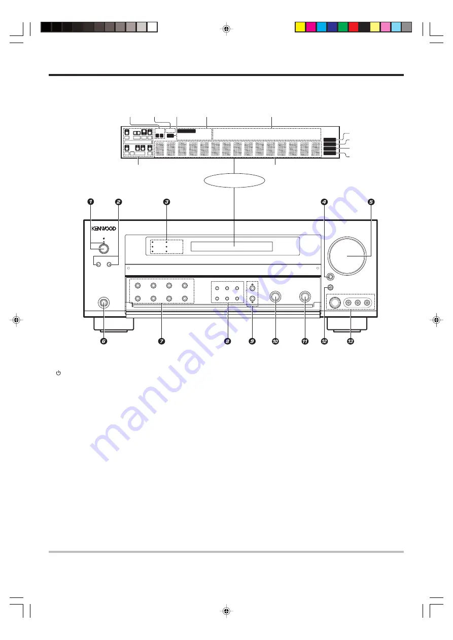
Display

*

Input channel indicators

Output channel indicators

AUTO indicator
MEMORY indicator

STEREO indicator

TUNED indicator

Frequency display
Input display
Preset channel display
Surround mode display

Speaker
indicators

MUTE
indicator

CLIP
indicator

Input mode
indicators

*

Input channel indicators

Input channel indicators light
up according to the
incoming audio signals.
"S" indicator will light up
when the surround compo-
nent of the audio signals is
only 1 channel.

Main unit

The figure is the view when the front cover is open

.

1

 (POWER ON/STANDBY) key

&

Use to turn the power ON/STANDBY.

Standby indicator

2

SPEAKERS A/B keys

)

Use to turn the A/B speakers on or off.

3

Surround LED (lighting-emitting diode)
indicators
DSP indicator

ª

Lights when the receiver is in the DSP mode.

96kHz fs indicator

¤

Lights when the receiver is in the 96kHz
LPCM playback mode.

ACTIVE EQ indicator

Lights when the receiver is in the ACTIVE EQ
mode.

DOLBY DIGITAL indicator

ª

Lights when the receiver is in the Dolby
Digital mode.

DTS indicator

ª

Lights when the receiver is in the DTS mode.

LOUDNESS indicator

¡

Lights when the LOUDNESS is ON.

4

INPUT SELECTOR key

)

Use to select input sources.

5

VOLUME CONTROL knob

)

6

PHONES jack

¡

Use for headphone listening.

7

LOUDNESS key

¡

Use to switch the status of LOUDNESS.

DOLBY VIRTUAL key

º

Use to select the Dolby Virtual Speaker and
the Dolby Headphone setting.

STEREO key

Use to switch the listen mode to STEREO.

INPUT MODE key

8)

Use to select the Input mode.

BASS BOOST key

¡

Use to select BASS BOOST setting.

DSP key

Use to select any of the DSP mode.

ACTIVE EQ key

¡

Use to select ACTIVE EQ setting.

DIMMER key

Use to select the REC MODE.

£

Use to adjust the brightness of the display.

8

SOUND key

&⁄

Use to adjust the sound quality and the
ambience effects.

TONE key

¡

Use to switch the status of TONE control.

SETUP key

&

Use to select the speakers' settings etc.

BAND key

¢

Use to select the broadcast band.

AUTO/MONO key

¢

Use to select the auto or manual tuning
mode.

MEMORY key

¢

Use to store radio stations in the preset
memory.

9

5

/

 keys

&

Use for  selection adjustments during sound,
set up and preset channel functions.

0

MULTI CONTROL knob

Use to control a variety of settings.

!

LISTEN MODE knob

Use to select the listening mode.

@

AV AUX/GAME key

^)

Use to switch the input to AV AUX or GAME.

#

AV AUX(S VIDEO, VIDEO, L-AUDIO-R)
jacks

^

Listen mode  indicators
SLEEP indicator

*5551/01-09/EN

05.2.8, 3:51 PM

6

Summary of Contents for VR-9060

Page 1: ...o effectively use the remote control it is important to read the operating instructions and obtain a proper understanding of the remote control and how to switch its operation modes etc Using the remote control without completely understanding its design and how to switch the operation modes may result in incorrect operations Register Online Register your Kenwood Home Audio product at www kenwoodu...

Page 2: ... INTENDED TO ALERT THE USER TO THE PRES ENCE OF IMPORTANT OPERATING AND MAINTENANCE SERVICING INSTRUCTIONS IN THE LITERATURE ACCOM PANYING THE APPLIANCE FCC WARNING This equipment may generate or use radio frequency energy Changes or modifications to this equipment may cause harmful interference unless the modifications are expressly approved in the instruction manual The user could lose the autho...

Page 3: ...component 20 Input level adjustment analog sources only 21 Adjusting the sound 21 Recording 22 Recording audio analog sources 22 Recording video 23 Recording audio digital sources 23 Listening to radio broadcasts 24 Tuning radio stations 24 Presetting radio stations manually 24 Receiving preset stations 25 Receiving preset stations in order P CALL 25 Ambience effects 26 Surround modes 26 Surround ...

Page 4: ...ation of the system installation to prevent malfunction Before applying the power Loading the batteries 1 Remove the cover 2 Insert the batteries 3 Close the cover Insert two AAA size R03 batteries as indicated by the polarity markings Preparing the remote control Operating range Approx Remote sensor Infrared ray system RECEIVER ON 6 m Unpacking Unpack the unit carefully and make sure that all acc...

Page 5: ...n you connect a game machine to the AV AUX jacks on the front panel the input selector of the receiver switches automatically to GAME and the optimum sound field for enjoying games is set This feature improves your convenience in playing video games Universal IR InfraRed remote control In addition to the basic receiver the remote control supplied with this receiver can also operate almost all of y...

Page 6: ...ators DSP indicator ª Lights when the receiver is in the DSP mode 96kHz fs indicator Lights when the receiver is in the 96kHz LPCM playback mode ACTIVE EQ indicator Lights when the receiver is in the ACTIVE EQ mode DOLBY DIGITAL indicator ª Lights when the receiver is in the Dolby Digital mode DTS indicator ª Lights when the receiver is in the DTS mode LOUDNESS indicator Lights when the LOUDNESS i...

Page 7: ...y Use to switch the remote control unit to the receiver control mode LISTEN MODE fi keys Use to select the listening mode STEREO key Use to switch the Listen mode temporary to the Stereo mode DSP MODE key º Use to select any of the DSP mode SOURCE key Use to turn the other source components on or off LED Blinks to show that signals are being trans mitted TV key Use to turn the TV on or off DISC SKI...

Page 8: ...n Please note that the following items will be deleted from the unit s memory if the power cord is disconnected from the AC outlet for approximately 1 day Power mode Input selector settings Speaker ON OFF Volume level BASS TREBLE INPUT level TONE ON OFF LOUDNESS ON OFF Dimmer level Listen mode setting Speaker settings Distance setting Input mode setting Sound mode settings Broadcast band Frequency...

Page 9: ...position Front Speakers are required for all surround modes Center Speaker Place front and center This speaker stabilizes the sound image and helps recreate sound motion Required for surround playback Surround Left and Right Speakers Place at the direct left and right or slightly behind the listening position at even heights approximately 1 meter above the ears of the listeners These speakers recr...

Page 10: ...OR CD DVD DIGITAL IN DIGITAL OUT DVD 6CH VIDEO 2 MONITOR DVD DVD MONITOR Connecting a DVD player 6 channel input If you have connected a DVD player to the receiver with digital connection be sure to read the Input mode settings section carefully 8 FRONT OUT L R S VIDEO OUT COAXIAL DIGITAL OUT AUDIO DVD Player S VIDEO cord SURROUND OUT L R VIDEO OUT CENTER OUT SUBWOOFER OUT Setting up the system Fo...

Page 11: ... system CAUTION Be sure to adhere to the following or proper ventilation will be blocked causing damage or fire hazard Do not place any object impairing heat radiation onto the top of the unit Leave a space around the unit from the largest outside dimension including projection equal or greater than shown below Top panel 50 cm Side panel 10 cm Back panel 10 cm The earth terminal with the H symbol ...

Page 12: ...the S VIDEO Jacks to make connections to video c o m p o n e n t s w i t h S VIDEO IN OUT Jacks If you use the S VIDEO jacks to connect your video play back components be sure to use the S VIDEO jacks when connecting your monitor and video recording components Video IN Setting up the system Video Audio DVD Player or LD Player DVD Player or LD Player A video component with digital audio outputs sho...

Page 13: ...r PCM OPTICAL DIGITAL OUT Setting up the system RF digital demodulator Commercially available DVD Player or CD Player Optical fiber cable Component with DTS Dolby Digital or PCM COAXIAL DIGITAL OUT Optical fiber cable COAXIAL DIGITAL OUT AUDIO To connect an LD player with a DIGITAL RF OUT connect the LD player to the RF digital demodulator Commercially available Next connect the DIGITAL OUT jacks ...

Page 14: ...nts to the COMPONENT jacks Monitor TV with component jacks Video Recorder DVD Recorder Satellite Cable Tuner Game Player with component jacks DVD Player with component jacks Video Recorder DVD Recorder Satellite Cable Tuner Game Player with component jacks DVD IN VIDEO 3 IN MONITOR OUT VIDEO 2 IN CR CB Y CR CB Y CR CB Y CR IN CB IN Y IN CR OUT CB OUT Y OUT CR OUT CB OUT Y OUT CR OUT CB OUT Y OUT C...

Page 15: ...ect SB LARGEx1 or SB NORMALx1 at Speaker settings Connecting the speakers Setting up the system Right Front Speakers B Powered Subwoofer Left Left Right Left To make sure that each speaker has been connected properly pay attention to the test tone from each speaker Refer to 6 Adjust the speaker volume level When you wish to connect the second pair of Front speakers or to connect the speakers in a ...

Page 16: ...oop Antenna Place the supplied loop antenna as far as possible from the receiver TV set speaker cords and power cord and adjust the direction for best reception AM Antenna Terminal connections 1 Push lever 2 Insert cord 3 Release lever FM Indoor Antenna The supplied indoor antenna is for temporary use only For stable signal reception we recommend using an outdoor antenna Disconnect the indoor ante...

Page 17: ...setting mode to the receiver is OFF The initial setting is SUBW ON When the setting SUBW OFF is selected the Front Speakers are automatically set to FRNT LARGE and the procedure skips to step 6 WhenSubwooferoutputsoundisrequired select FRNTNORMAL or select both FRNT LARGE and SW RE MIX ON After setting SW Subwoofer from OFF to ON SB SW AMP setup display will appear to enable you to re select eithe...

Page 18: ...main setup displays Preparing for surround sound 8 Use the MULTI CONTROL knob or MULTI fi keys to select the appropriate Surround Speaker setting If you selected FRNT LARGE as the Front Speaker setting 1 SURR NORMAL Average size Surround Speakers are con nected to the receiver 2 SURR LARGE Large size Surround Speakers are con nected to the receiver 3 SURR OFF Surround Speaker setting mode to the re...

Page 19: ...TE A B CLIP SW LFE STEREO Indication in feet Indication in meters The allowable setting range is 1 to 30 feet 0 3 to 9 0 m adjustable in 1 foot 0 3 m increments 4 Repeat steps 3 to input the distance for each of the speakers 5 Press the SETUP key again to return to main setup displays The speakers you have selected should appear on the display Confirm that all the speakers have been correctly sele...

Page 20: ...paring for playback Some preparatory steps are needed before starting playback Turning on the receiver 1 Turn on the power to the related components 2 Turn on the power to this receiver by pressing the POWER ON STANDBY key Selecting the input mode If you have selected a component connected to the CD DVD VIDEO 2 VIDEO 3 or DVD 6CH jacks make sure that the input mode setting is correct for the type ...

Page 21: ...djustment can be made when the receiver is in the PCM stereo and analog stereo mode Press the LOUDNESS key to turn the LOUDNESS setting ON This function is available only for speakers connected to FRONT A terminals To cancel Press the LOUDNESS key again so that the LOUDNESS indicator goes off Input level adjustment analog sources only MULTI CONTROL SOUND SOUND RCV MODE INPUT SELECTOR Input Selecto...

Page 22: ...EQ CINEMA Effective when watching movie The ACTIVE EQ indicator lights up 3 ACTIVE EQ GAME Effective when playing video game The ACTIVE EQ indicator lights up 4 ACTIVE EQ OFF The ACTIVE EQ function is turned OFF The ACTIVE EQ indicator goes off ACTIVE EQ will scroll from right to left ACTIVE EQ function will not be available when in REC MODE or when searching or presetting radio stations Listening...

Page 23: ...CM are identified automatically and converted into stereo signals that are ready for recording 3 REC MODE MANUAL The input signal type at the moment this mode is selected is held throughout this mode When the REC MODE MANUAL is selected the digital input signal is converted to stereo signals down mix But once the digital signal is changed to other signal no signal is output When the REC MODE AUTO ...

Page 24: ...ys or TUNING 1 keys to select the station STEREO lights when a broadcast is being received in stereo AUTO MEMO STEREO TUNED STEREO TUNED is displayed when a station is received Auto tuning The next station is tuned automatically Manual tuning Turn the knob or use the MULTI fi keys to select the desired station Presetting radio stations manually MULTI CONTROL MEMORY INPUT SELECTOR Input Selector key...

Page 25: ... CALL or 4 key lets you skip through the presets receiving each preset station at 0 5 second inter vals Receiving preset stations Numeric keys TUNER 1Press the TUNER key to select tuner as the source 2Enter the number of the preset station you want to receive up to 40 Press the numeric keys in the following order For 15 press 0 5 For 20 press 0 0 If you make a mistake entering a two digit number p...

Page 26: ...Center Speaker R Front Right Speaker SL Surround Left Speaker SR Surround Right Speaker SB Surround Back Speaker SBL Surround Back Left Speaker SBR Surround Back Right Speaker The below speaker placements are for 6 1 channel surround sound system which are Dolby Digital EX Neo 6 DTS ES DSP mode The below speaker placements are for 7 1 channel surround sound system which is Dolby Pro Logic IIx With...

Page 27: ...c surround effects DTS The DTS multi channel audio format is available on CD LD and DVD software DTS is a strictly digital format and cannot be decoded inside most CD LD or DVD players For this reason if you attempt to listen to DTS encoded software through the analog output of your new CD LD or DVD player you will experience digital noise in most cases This noise can be quite loud if the analog o...

Page 28: ...mark and Dolby Digital format digital broadcasts etc Dolby Pro Logic can be used when playing video DVD or LD software bearing the mark Input Selector keys DSP LISTEN MODE INPUT MODE STEREO INPUT SELECTOR LISTEN MODE fi INPUT MODE DSP MODE STEREO Preparations Turn ON related components Complete Preparing for surround sound speaker settings Use the INPUT SELECTOR key or Input Selector keys to selec...

Page 29: ... surround MUSIC mode 6 PLII GAME Pro Logic II surround GAME mode 7 PRO LOGIC Pro Logic surround 8 NEO 6 CINEMA Neo 6 surround CINEMA mode 9 NEO 6 MUSIC Neo 6 surround MUSIC mode 0 STEREO Normal stereo playback Dolby Digital or DTS signal having more channels than the maximum number of playback channels available using the receiver s current settings is input downmixing is performed to match the nu...

Page 30: ...n you use only two speakers or listen through headphones In the Dolby Virtual Speaker and Dolby Headphone modes only the listen modes for 2 channels can be selected Also the desired listen mode may be unable to be selected depending on the reproduced signals DOLBY VIRTUAL DOLBY VIRTUAL PHONES How to set the Dolby Virtual Speaker mode when not using headphones Press the DOLBY VIRTUAL key for the fo...

Page 31: ...ND key to return to the input indication Adjusting the sound You can make further adjustments to the sound while listening to playback in the surround mode STEREO SOUND DIMMER LISTEN MODE fi MULTI fi DIMMER SOUND LISTEN MODE MULTI CONTROL STEREO RCV MODE SLEEP 1 For the remote control press the RCV MODE key to switch to receiver mode 2 Press the SOUND key and then use the 5 5 5 5 5 keys or MULTI key...

Page 32: ...e listen mode is set to DSP mode 96kHz LPCM will appear in the display and no sound can be heard from the speakers Use the LISTEN MODE knob LISTEN MODE key or STEREO key to select STEREO mode to output sound from the speakers Dimension mode Pro Logic IIx Music and Pro Logic II Music mode only When listening to music with certain recordings you will also be able to achieve a suitable balance from a...

Page 33: ... The sleep timer function turns the receiver OFF to the standby mode automatically when the set timer period has elapsed The sleep timer period can be set in 10 minute steps up to 90 minutes Press the SLEEP key repeatedly until the desired period before turning the receiver OFF standby mode is displayed Each press increments the sleep timer period by 10 minutes 10 20 30 70 80 90 Cancel 10 20 The S...

Page 34: ...s not work try searching for the code 5Repeat steps 2 to 4 to register additional components until all components have been registered Note Although each setup code is designed to work with a number of different models certain codes may not work with some models Also certain codes may only operate some of the functions available on a given model Searching for your codes If your component does not ...

Page 35: ...us page for the combination of source keys and the other components assignment 4To re assign other device keys repeat steps 1 through 3 by substituting the key sequence from the below chart for the most popular components To re assign key Sequence Perform TV MODE as 2nd VIDEO 1 key REMOTE SETUP 9 9 2 VIDEO 1 TV MODE TV MODE as 2nd VIDEO 2 key REMOTE SETUP 9 9 2 VIDEO 2 TV MODE TV MODE as 2nd CD DV...

Page 36: ...o 0092 Akai 0812 0702 0030 0672 Albatron 0843 0700 America Action 0180 Anam 0180 AOC 0030 Apex Digital 0748 0765 1943 Audiovox 0451 0180 0092 0623 Bell Howell 0154 BenQ 1032 Bradford 0180 Broksonic 0236 0463 1935 Candle 0030 Carnivale 0030 Carver 0054 Celebrity 0000 Celera 0765 Changhong 0765 Citizen 0060 0030 0092 Clarion 0180 Commercial Solutions 1447 0047 Contec 0180 Craig 0180 Crosley 0054 Cro...

Page 37: ... 0700 Megatron 0178 0145 Memorex 0154 0463 0150 0178 MGA 0150 0030 0178 Midland 0047 0017 0051 Mitsubishi 0093 1250 0150 0178 Monivision 0843 0700 Motorola 0093 MTC 0060 0030 Multitech 0180 NAD 0156 0178 NEC 0030 1704 Nikko 0030 0178 0092 Norcent 0748 0824 NTC 0092 Onwa 0180 Optimus 0154 0250 0166 Optoma 0887 Optonica 0093 Orion 0236 0463 Panasonic 0250 0051 1946 1941 1947 Penney 0047 0156 0051 00...

Page 38: ...nt 0476 0276 0003 GoldStar 0144 Hamlin 0009 0273 Jerrold 0476 0276 0003 Memorex 0000 Motorola 0476 0276 1376 Multitech 0883 Pace 1877 0237 Panasonic 0000 0107 Paragon 0000 Philips 0317 1305 Pioneer 1877 0877 0144 0533 Pulsar 0000 Quasar 0000 RadioShack 0883 Regal 0279 0273 Runco 0000 Samsung 0144 Scientific Atlanta 1877 0877 0477 0008 Sony 1006 Starcom 0003 Supercable 0276 Supermax 0883 Torx 0003 ...

Page 39: ...37 0000 Thomas 0000 Tivo 0618 1503 0739 0636 TMK 0240 Toshiba 0045 0043 1503 1972 Totevision 0037 0240 Touch 1972 Unitech 0240 Vector 0045 Video Concepts 0045 Videomagic 0037 Videosonic 0240 Viewsonic 1972 Villain 0000 Wards 0060 0035 0048 0047 0081 0240 0000 0042 White Westinghouse 0209 XR 1000 0035 0000 Zenith 0039 0033 0000 0209 ZT Group 1972 Video Accessories Macro Image Technology 1383 Motoro...

Page 40: ...ks 3 8 Play Skip 4 Skip DISC SEL Disc selection TOP MENU Title RETURN 8 Pause 100 Select tracks DOLBY VIRTUAL AUDIO SUBTITLE ANGLE ON SCREEN STANDBY RECEIVER ON SOURCE DISC SKIP LAST TV DISC SEL INPUT SEL INPUT MODE TV INPUT TV MUTE TV VOL INFO LOUDNESS MUTE BASS BOOST TONE ANGLE VOLUME SUBTITLE AUDIO ENTER MULTI MULTI BAND AUTO MONO SLEEP P CALL TUNING DIMMER DVD 6CH VIDEO 1 VIDEO 2 VIDEO 3 AV AU...

Page 41: ...PUT SEL Input selection Numeric keys SOURCE Source power 1 Search Search 7 Stop 3 8 Play 8 Pause Record INFO Information STANDBY RECEIVER ON SOURCE DISC SKIP LAST TV DISC SEL INPUT SEL INPUT MODE TV INPUT TV MUTE TV VOL INFO LOUDNESS MUTE BASS BOOST TONE ANGLE VOLUME SUBTITLE AUDIO ENTER MULTI MULTI BAND AUTO MONO SLEEP P CALL TUNING DIMMER DVD 6CH VIDEO 1 VIDEO 2 VIDEO 3 AV AUX PHONO MD TAPE CD D...

Page 42: ...p fi Cursor down Cursor left Cursor right CHANNEL EXIT ENTER GUIDE MENU LAST Last channel INPUT SEL Input selection Numeric keys SOURCE Source power 8 Pause 1 Rewind Fast Forward 7 Stop Record 3 8 Play DOLBY VIRTUAL INFO Display STANDBY RECEIVER ON SOURCE DISC SKIP LAST TV DISC SEL INPUT SEL INPUT MODE TV INPUT TV MUTE TV VOL INFO LOUDNESS MUTE BASS BOOST TONE ANGLE VOLUME SUBTITLE AUDIO ENTER MUL...

Page 43: ...VIDEO 2 VIDEO 3 AV AUX PHONO MD TAPE CD DVD TV MODE RCV MODE TUNER PAGE DOLBY VIRTUAL DSP MODE REMOTE SETUP ACTIVE EQ STEREO LISTEN MODE RC R0829 TOP MENU SETUP RETURN EXIT ON SCREEN GUIDE MENU SOUND CHANNEL REMOTE CONTROL UNIT Numeric keys Select tracks 3 8 Play Skip 4 Skip 8 Pause 1 Search Search SOURCE Source power 7 Stop Record 100 Select tracks STANDBY RECEIVER ON SOURCE DISC SKIP LAST TV DIS...

Page 44: ...44EN 5551 34 48 EN 05 2 7 6 24 PM 44 ...

Page 45: ...nected The speaker is not set up correctly The surround speaker cords and or the center speaker cord is disconnected The speaker is not set up correctly A surround mode has not been engaged The surround and or center volume controls are set to the minimum level The audio cord from the record player is not connected to the PHONO jacks The record player is not grounded There are many possible causes...

Page 46: ...ot been set to the operation mode for the component you wish to control Remedy Register a setup code at the respective input s Press the RCV MODE key to select the appropriate operation mode Replace with new batteries Operate the remote control unit within the controllable range Place the disc or tape in the source component which you want to play Wait until recording has completed Press any of th...

Page 47: ...m 660 nm 30 nm Coaxial 0 5 Vp p 75 Ω Output level impedance wave length Optical 21 dBm 15 dBm 660 nm 30 nm 100 watts per channel minimum RMS both channels driven at 8 Ω from 20 Hz to 20 kHz with no more than 0 09 total harmonic distortion FTC VIDEO section VIDEO inputs outputs VIDEO composite 1 Vp p 75 Ω S VIDEO inputs outputs S VIDEO luminance signal 1 Vp p 75 Ω S VIDEO chrominance signal 0 286 V...

Page 48: ...he spaces designated on the warranty card and in the space provided below Refer to the model and serial numbers whenever you call upon your dealer for information or service on this product Model__________________ Serial Number________________________ 5551 34 48 EN 05 2 7 6 25 PM 48 ...

Reviews: