4
02 RECEPTION CIRCUIT
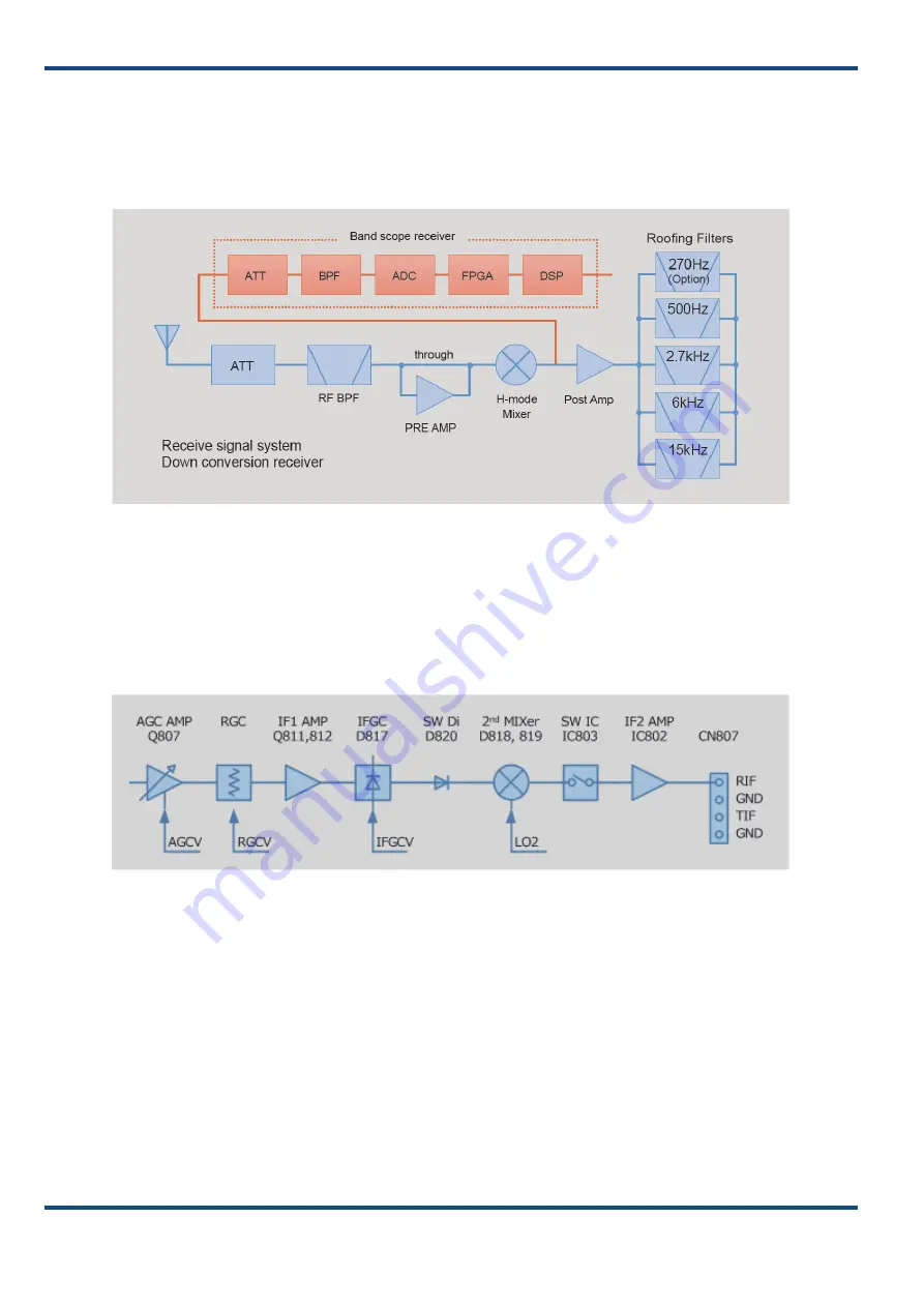
The received signal which was input from the antenna comes into the front-end block of the receiver through the
antenna switching circuit. The bandpass filter for the selected receive band eliminates interfering signals outside the
band. The received signal is amplified by a pre-amplifier and is then converted to the first IF signal (8.248 MHz) by the
first H-mode mixer having high IP characteristics.
The “Block Diagram of the Front-end Circuit for the Receiver” is shown below:
Fig. 1 Block Diagram of the Front-end Circuit for the Receiver
The first IF signal enters the roofing filter through the bandscope branching circuit and the post-amplifier, and the
adjacent interfering signals outside the band is eliminated.
The “Block Diagram of the IF Circuit for the Receiver” shown below shows the circuit configuration subsequent to the
roofing filters. The first IF signal routes through the AGC amplifier and the first IF amplifier to the second mixer, which
converts it to the second IF signal (24 kHz/36 kHz). The second IF signal enters the DSP as the baseband signal through
the second IF amplifier, and the AGC response, all-mode demodulation, and audio signal processing, etc. are done.
Fig. 2 Block Diagram of the IF Circuit for the Receiver


