10
Connection of Equipment
Chapter 1: Connection of Equipment
T V S C A RT
Y
C
R
C
B
V C R S C A RT
C OA X I A L
COMPONENT
VIDEO OUTPUT
DIGITAL OUTPUT
(PCM/BIT STREAM)
INTERFACE
PROGRESSIVE
O P T I C A L
S VIDEO OUTPUT
1
2
VIDEO
OUTPUT
6 C H . O U T P U T
COMPONENT VIDEO OUTPUT
FRONT
SURROUND
SUB WOOFER
CENTER
M I X L I N E
O U T P U T
1
2
L
R
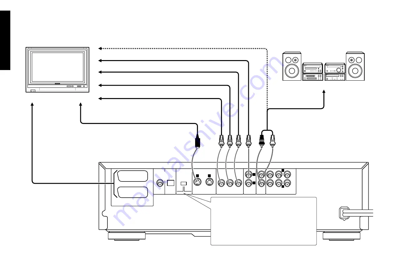
Connection with a TV or Stereo System
S Video cable (provided)
Video cable (optional)
Audio cable (provided)
Audio connection:
To audio input jacks
Video connection:
To video input jack
Audio cable (provided)
Audio connection:
To audio input jacks
Video cable (optional)
Video cable (optional)
Video cable (provided)
Component video connection:
To color difference (C
R
) input jack
TV
Stereo system
To color difference (C
B
) input jack
To luminance (Y) input jack
Select the video connection method
according to the TV in use. When S-Video
cable is connected, the ordinary video
connection is not necessary.
S Video connection:
To S Video input connector
SCART connection (For U.K. and Europe):
Connect the
TV SCART
connector to the TV's input connector.
Connect the
VCR SCART
connector to the VCR's input
connector.
Select the scanning method of the Component Video output
using the
COMPONENT VIDEO OUTPUT
switch on the
rear panel.
INTERLACE
: Scanning method is fixed at interlaced
scanning.
PROGRESSIVE
: When progressive scanning is unavailable
with certain discs, the scanning method is switched
automatically to interlaced scanning. When the scanning
method is changed, the scanning status will be displayed
for a few seconds.


