background image

AE

AG

AI

AK

AM

AF

AH

AJ

AL

AN

7.8V

7.6V

7.6V

-6.4V

-6.4V

-6.4V

4.2V

4.2V

0.4V

0.3V

3.0V

3.0V

5.1V.

5.1V

11.3V

LOADING:6.7V

NORMAL:5.3V

LOADING:0V

NORMAL:4.7V

LOADING:4.0V

NORMAL:0V

6.0V

10.7V

6.5V

-36.5V

-31.6V

31.0V

10.7V

8.8V

8.1V

8.1V

3.4V

-13.0V

-8.3V

-8.9V

-6.4V

-3.8V

-6.5V

-8.0V

-31.0V

-30.8V

-23.1V

-18.6V

-26.5V

-14.9V

-22.4V

2.4V

2.0V

5.1V

4.2V

5.1V

5.1V

0.2V

5.1V

2.8V

5.1V

REC:5.1V

PLAY:0V

5.1V

5.1V

5.1V

0.8V

3.0V

4.2V

0.4V

3.7V

5.1V

1.8V

5.1V

5.1V

CNP473

D509

D513

UN970

AVR

-31V

PLAY OUT

SW901

SW501

D651

7.5V AVR

LINE

Rch

Lch

Q653

MUTE
DRIVE

T551

D504

Q503

Q504

D505

5V AVR

5V AVR

7V AVR

-7V AVR

Q501

(E/T)TYPE

(J)TYPE

D506

D512

D502

Q505

Q506

D507

D510

D508

D551

D552

D553

D554

Q502

D501

CNP472

CNP471

D555

T551

AMP

PHONES

(2/2)

IC651

IC651
(1/2)

J101

PHONES
MUTE

D503

Q602

Q601

(1/2)

IC601

IC601
(2/2)

Q452

Q451

CNP902

CNW903

PHONES

CNW901

J981

PHONES

LEVEL

LEVEL

REC

SENSOR

REMOTE

RESET IC

Q902

Q901

SW961

SW957

NAME

(JOG DIAL)

MULTI CONTROL

TIME
DISPLAY

DISPLAY/
CHARAC

DELETE

TIMER/

ENTER

SW956

SW959

SW960

SW958

REC

SW951

SW952

SW953

SW954

4c

14G

13G

4b

6a

5a

3a

2a

1a

7G

8G

9G

10G

11G

12G

: 2SD2012Y(FIN)

: NJM45600

D651 

: SR19

D551-555 

: RL104A

               : ISS133

D509,510,512,513 

D508

D507 

D506

D505

D504

D503 

D502

D501

D301 

: MTZJ2700

: MTZJ5R8C

: MTZJ7R58

: MTZ6R8A

: MTZ9R19

: MTZ9R18

: MTZJ3308

: MTZJ6R88

: MTZJ5R18

Q653

Q505

Q504,506

Q503

Q502

Q501

Q451,452,601,602 

IC601

IC501

IC302

IC301

: KRC102M

: KRC1024M

: 2SD488-C

: 2SB582-C

: KTA1266GR

: 2SC28788

: NJM45800

: ISB1233SOYX

: 74HC10AP

: 74HCU04

IC201

: uUDA1340

IC101,651

MAIN SECTION

DISPLAY SECTION

IC501

HEADPHONE

IC902

66

72

0.8

R503

1.8K

C505

+

10u50

+5V

+5V

1

+

100u10

+

C518

100u10

C220

1000P

C222

0.022

+

C522

1000u6.3

R509

820

+

C502

4700u25

+

C521

4700u25

+

C501

100u25

R926

1K

-31V

R945

47K

-31V

-31V

R504

50/60Hz

50Hz

AC230V~

C512

100

C525

+

C666

100u10

R960

5.6K

R921

R922

G

A

B

8.2

-BV

+

C514

10u16

+

1u50

C221
0.022

C667

0.1

0.022

R669

2.7K

R670 330

F552 T1.0A 250V

C519

F551

HLD551

HLD552

HLD554

HLD553

HLD551

HLD552

HLD554

HLD553

F551

T1.0A 250V

+5V

+5V

+7.5V

+7V

+7V

+7V

+7V

+7V

+7V

+7V

-31V

-31V

-7V

-7V

-7V

-7V

-7V

+7V

+7V

100

R508

680

R507

+

C511

47u25

0.022

C530

100

R510

C513 47u25

+

47K

R615

R616

47K

R610

1K

1K

R609

13

14

15

6

8

10

1

9

4

5

3

7

3

4

+BV

+BV

+7V

+7V

+7V

-BV

-BV

-BV

+BV

+BV

+BV

L202

10uH

14

12

11

1

2

3

4

5

6

7

8

9

10

24

23

21

22

18

17

19

20

16

15

13

R512

470

+

C517

100u10

+

C507

33u50

+

C504

220u50

R501

R511

+

C524

1000u6.3

33K

R514
100K

C520

R516
220K

1000P

+

C613

47u10

680

100

R506

R505

1

2

4

3

P MUTE

-31V FL VP

DAC CLK

D-1.2

u-CON GND

BUCK UP 5V

AD5V

FIL1

DAC DATA

P-IN

MD DSTB

MD 7.5/5V

MD K-DATA

MD DSCK

DFS

DAC MODE

FIL2

MD DATA

MD 5-10

MD LOAD

MD SYN

P-CNT

MD RESTE

MD P-OUT

RESET

LOAD SW

BUCK UP

PDOWN

10u16

C515

2

1

+

10u16

C516

OUT

IN

GND

3

C223

0.022

+

R518

220

R517

220

AC100V

F552 1A 125V

1A 125V

+

C656

10u16

1K

R654

+

C655

10u16

R653

1K

150P

100K

R652

C652

C651

100K

R651

150P

C654

27P

R659

10

27P

C653

R682

1K

1K

R681

1

+

-

3

2

4

7

5

+

-

6

NC

RESET SW

HP AMP R OUT

HP AMP L OUT

HP AMP GND

AUX VR R OUT

GND

AUX VR L OUT

AUX AMP R GND

AUX AMP L IN

AUX AMP I GND

11

12

AUX AMP R IN

R668 82

8

10K

R457

R458

10K

8.2

R551

C561 0.01

C551

0.01

0.01

C552

+

C665

100u10

82

R667

R613

100

R614

+

C658

220u10

+

C657

220u10

C457

0.022

+

C509

47u25

+

C510
1u50

8.2

R502

R660

10

+

C614

47u10

R620

10K

R619

10K

R617

330

330

R618

R602

C602

+

220P

C604

470

47u10

+

47u10

C601

1

+

-

8

2

C607

R611

220P

3

R607

22K

R605

C603

220P

1K

+

1.5K

47P

C611

100u10

C615

R601

470

7

+

5

4

-

220P

1.5K

R612

C608

6

1K

R608

22K

R606

+

C612

C616

47P

100u10

C455

820P

470P

470P

33K

C459

C453

R453

+

C451

47u10

R455

R451

100

330

33K

47u10

C452

R452

820P

C456

R454

470P

C454

470P

C460

10

9

8

7

6

5

4

3

2

1

100

R456

330

+

X902

+5V

+5V

+5V

+5V

+5V

+5V

+5V

+5V

HP AMP R OUT

HP AMP L OUT

AUX AMP R GND

AUX AMP L IN

AUX AMP L GND

AUX AMP R IN

NC

RESET SW

AUX VR R OUT

HP AMP GND

AUX VR L OUT

GND OPEN

FILMNT 2

FILMNT 1

AD5V

BACK-UP5V

u-COM GND

-31V

D-1, 2

DAC CLK

DAC MODE

DAC DATA

DFS

MD DSCK

MD K-DATA

MD 7.5/5V

MD DSTB

P-IN

MD P-OUT

P-CNT

P MUTE

MD DATA

MD RESET

MD S-ID

MD LOAD

MD SYN

1000P

C915

1000P

C914

49

50

51

52

53

54

55

56

58

59

60

61

62

63

64

65

C983

0.1

1000P

C981

1000P

C982

3

2

1

VR981-2

VR901-2

VR901-1

R970

1K

+

C971

10u16

100P

C970

100

R971

29

R924

10K

10K

R972

470K

R923

10K

R920

470K

10K

3

2

1

IN

OUT

GND

R906

220K

0.1

C906

+

C907

1u50

77

76

75

74

73

70

69

68

67

71

68P

C904

12P

C905

33

31

RA928

1K

C903

0.1

C902

0.1

C901

0.1

C910

0.1

R902

10K

R901

92

R940

47K

93

R941

47K

94

R942

47K

95

R943

47K

96

R944

47K

97

10

14

15

16

18

20

21

23

29

30

RA927 1K

RA919 1K

RA925 1K

RA926 1K

0.01

C922

C923

0.01

RA918 1K

RA916 1K

RA914 1K

4.7M

R910

1.8K

R909

1K

RA933

1K

RA931

1K

RA930

RA913 1K

RA912 1K

RA908 1K

RA902 1K

RA903 1K

RA904 1K

6.8K

R904

12K

R903

R905

12K

R969

10K

R968

10K

3.9K

R959

1.2K

R955

1K

R954

1.5K

R956

1.8K

R957

R958

2.7K

1K

R950

1.2K

R951

1.5K

R952

1.8K

R953

15

14

16

18

20

21

23

31

30

33

44

43

42

41

24

23

21

22

20

19

17

16

15

14

13

12

11

18

10

9

8

7

6

5

4

3

2

1

11

10

2

1

3

12

9

8

7

6

5

4

3

2

1

72

74

73

P6

P5

P4

76

75

78

77

P2

P1

P26

80

79

82

81

P28

P29

P30

P27

84

83

86

85

IC

NX

NX

NX

88

87

89

NX

NX

NX

NP

P3

91

93

92

NP

F1

F1

F1

94

90

23

5G

22

6G

21

7G

20

8G

19

9G

18

10G

17

11G

16

12G

15

13G

14

14G

13

15G

12

P36

11

P35

10

P34

9

P33

8

P32

7

P31

6

IC

5

NP

4

NP

3

F1

2

F1

1

F1

VREF

VEE

USEG19

USEG20

USEG21

USEG22

USEG23

USEG24

AVSS

DFS0/DFS1

(MD) DSTB

P-CNT

P-IN

(MD) LO/EJ

(MD)MD DATA

(MD) K-DATA

(MD) DSCK

DAC DATA/EX

DAC CLK/EX

DAC MODE

DIG SEL 2

DIG SEL 1

JCG AD

INI/MUTE IN

KEY4

KEY3

KEY2

KEY1

30

29

28

27

26

25

24

23

22

21

20

19

18

17

16

15

14

13

12

11

10

9

8

7

6

5

4

3

2

1

XCOUT

XCIN

RESET

P MUTE

RX-IN

P OUT

37

36

35

34

33

32

31

92

93

94

95

96

97

98

99

100

+

C920

10u16

L901
22uH

+

C909

1u50

C908

1

10

TIMER REC

RANDOM

REMAIN

TOTAL

MONO LP PRGM

-

DATE

TRACK

DISC

TOC

(

)

(

)

(

)

(

)

(

)

(

)

(

)

(

)

)

(

(

)

)

)

)

(

(

(

)

)

(

(

(

)

(

)

(

)

(

)

(

)

(

)

(

)

(

)

(

)

(

)

(

)

(

)

(

)

(

)

(

)

(

)

(

)

)

(

)

(

)

(

)

(

)

(

)

(

)

(

)

(

)

(

)

(

)

(

(

)

(

)

)

(

)

(

)

(

)

(

)

(

)

(

(

)

(

)

(

)

(

)

(

)

(

)

(

)

(

)

)

(

)

(

(

)

(

)

(

)

(

)

(

)

(

)

(

)

(

)

(

)

(

)

(

)

(

)

(

)

)

(

(

)

(

)

PCB/SD 

2P 


97.11.29 

2:05 

AM 

 y [ W  

5

Summary of Contents for DM-3090

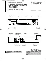
Page 1: ...ONTROL TIME DISPLAY DISPLAY CHARAC TRACK EDIT ON STAND BY STEREO MINIDISC RECORDER TIMER DELETE ENTER REC REC LEVEL 0 10 PHONES LEVEL MIN MAX PHONES R L R L PLAY OUT REC IN DIGITAL LINE 2 REC IN 1 REC IN PLAY OUT OPT RESET KENWOOD badge B43 0302 04 Front glass B10 2457 08 Front panel A60 1370 08 Knob JOG K29 6946 08 Knob REC HP K29 6947 08 AC power cord bushing J42 0338 08 AC power cord E30 Optica...

Page 2: ...ectly This is not a malfunction however and the unit should be dried To do this turn the POWER switch ON and leave the unit as it is for several hours Be especially careful in the following conditions When the unit is brought from a cold place to a warm place and there is a large temperature difference When a heater starts operating When the unit is brought from an air conditioned place to a place...

Page 3: ...key Stop key Cue Review key TOC DISC TOTAL REMAIN RANDOM TIMER REC CLOCK TRACK DATE 0dB OVER 12 4 MONO LP PRGM 1 8 15 2 9 16 3 10 17 4 11 18 5 12 19 6 13 20 7 14 1 2 3 4 5 6 7 8 9 0 1 Pause indicator 2 Record indicator 3 Play indicator 4 Monaural Long Play Mode indicator 5 Programme indicator 6 Repeat indicator 7 Total Time Remaining Time indicator 8 Random indicator 9 Timer Playback Timer Recordi...

Page 4: ...basic operation keys as well as a variety of applied operation keys so that it can be used in a wide range of purposes Use care to store the remote control unit in a safe place so as not to lose it 1 POWER key 2 EJECT key 3 Numeric keys 6 Recording operation keys REC INPUT Input select key REC MODE Record mode key AUTO MARK Auto mark key REC CANCEL Record cancel key Plug the stereo headphones with...

Page 5: ...de of blue connector of loading motor push the rack gear in the arrow direction to move the cam plate lever until tick is heard 3 Remove the screw B1 x1 pc and the spring B2 x1 pc fitted to the holder arm and shift the cartridge holder to the left side to remove it How to remove the mechanism switch PWB See Fig 10 3 1 Remove the screws C1 x 2 pcs and remove the mecha nism switch PWB Figure 10 1 Fi...

Page 6: ...he spindle motor See Fig 11 2 1 Remove the screws E1 x 3 pcs and remove the spidle motor Caution Be careful so that the turntable is not damaged How to remove the optical pickup See Fig 11 3 1 Remove the screws F1 x 3 pcs Caution Be careful so that the gear is not damaged The damaged gear emits noise during searching Sled Motor Loading Motor D1 x2 Ø1 7x2mm D1 x2 Ø1 7x2mm Spindle Motor Turntable E1...

Page 7: ... D GND DSTB MDDATA KDATA 4M DRAM ENDEC ATRAC IC1201 LR37648 OSCILLATOR XL1201 33 8688MHz SW1956 SW1955 SW1954 SW1953 SW1952 Q1251 Q1254 MD RECORDING HEAD M901 SPINDLE MOTOR M902 SLED MOTOR M903 LOADING SWITCH RECSWITCH PLAYSWITCH LEAD INSWITCH A BSIGNAL E FSIGNAL RF1 RF4SIGNAL HEAD DRIVE SIGNAL IC1251 IC1101 IR3R55 RF SIGNAL PROCESSOR LOADING MOTOR HEAD UP DOWN M M DIRECT SWITCH WRITE PRO M LASER ...

Page 8: ...ET DSTB DSCK K DATA MD DATA FL DISPLAY B FL901 DIG SEG JOG KEY RX IN IC901 IX0196AW SYSTEM MICROCOMPUTER MD MUTE SW901 JOG SWITCH KEY IN BLOCK UN970 REMOTE SENSOR FL VP 31V A D 5V BACK UP 5V FL POWER CIRCUIT FL VP 32V FL DISPLAY B RECTIFYING CIRCUIT F551 1A L 250V F552 1A L 250V T551 POWER TRANSFORMER AC 230V 50Hz HEADPHINES J981 H P VOL VR981 IC651 NJM4560D OPE AMP Q451 Q452 MUTE J101 LINE OUT 3 ...

Page 9: ...ock signal input terminal 23 DATA Serial data input terminal 24 DVCC Digital section power terminal 25 FOUT Servo signal amp tracking servo system output terminal 26 EOUT Servo signal amp tracking servo system output terminal 27 BOUT Servo signal amp focus servo system output terminal 28 AOUT Servo signal amp focus servo system output terminal 29 TCGO Track cross detection signal amp output termin...

Page 10: ...KI Power supply for DRAM interface 32 22KO Output Address output to external D RAM ADR4 33 ADLPFO Output Address output to external D RAM ADR5 34 NC Output Address output to external D RAM ADR6 35 ADIPO Output Address output to external D RAM ADR7 36 ADIPI Output Address output to external D RAM ADR8 37 ADAGC Output Data output enable signal output to external D RAM 38 ADAGI Digital GND 39 RF2 1 O...

Page 11: ...ocus error signal monitor output 76 TOTMON Output Total signal monitor output 77 TEMON Output Tracking error signal monitor output 78 SBCK Input DIN subcode read clock EIAJ CP 309 Format 79 SBO Output DIN subcode serial data EIAJ CP 309 Format 80 SBSY Output DIN subcode block sync signal EIAJ CP 309 Format 81 SFSY Output DIN subcode frame sync signal EIAJ CP 309 Format 82 FOK Output Focus OK detec...

Page 12: ...TA1OUT Output LD loading motor control output 29 P71 TA0IN Input CIN track count signal input 30 P70 TA0OUT Input INN SW inner SW detection input 31 P67 TXD1 Output R DATA 32 P66 RXD1 Output R LATCH 33 P65 CLK1 Output R CLK 34 P64 CTS1 RTS1 Output DSTB system controller communication enable and communication beingexecuted CTS0 CLKS1 35 P63 TXD0 Output MD DATA MD Data Output 36 P62 RXD0 Input K DAT...

Page 13: ...14 D12 Output DFS0 output 77 P13 D11 Output DFS1 output 78 P12 D10 Output DIG EX output for CK 79 P11 D9 Output DIG CD output for CK 80 P10 D8 Output XRST system reset output 81 P07 D7 Output AD MUTE output for CK 82 P06 D6 Output EMPHA output for CK 83 P05 D5 Output DA MUTE output for CK 84 P04 D4 Output MUTE output 85 P03 D3 Output DOUTM output for CK 86 P02 D2 Input TEST2 special mode selection...

Page 14: ...t EMPHASIS information from MD 9 P67 SRDY1 CS DSTRB Input MD serial interface strobe signal SCLK12 0 P66 SCLK1 DSCK Output MD serial interface clock signal 1 P65 SOUT1 K DATA Output MD serial interface transmission signal 2 P64 SIN1 MD DATA Input MD serial interface reception signal 3 P63 CNTR1 MD LO EJ Output MD loading power voltage selection signal 4 P62 CNTR0 Output Not used 5 P61 PWM Output N...

Page 15: ...t 5V 92 97 PA5 SEG5 S19 S24 Output Segment for FL drive PA0 SEG0 98 VEE VEE Input 30V 99 AVSS AVSS Input GND 100 VREF VREF Input 5V 45 54 P23 DIG19 UDIG0 UDIG9 Output Digit for FL drive P12 DIG10 55 56 P11 SEG41 DIG9 UDIG10 UDIG11 Output Digit for FL drive P10 SEG40 DIG8 57 60 P07 SEG39 DIG7 UDIG12 UDIG15 Output Digit for FL drive P04 SEG36 DIG4 61 64 P05 SEG35 DIG3 S35 S32 Output Segment for FL d...

Page 16: ... occurred The TOC infomation on this disc does not meet the MD specifications or it cannot be read The TOC infomation could not be created properly due to a mechanical shock or to scratches on the disc The MD contains an error Music is not being recorded Replace the MD wiht a recoded disc Record using the analogue cable Change the stop position of the track and then try editing it Stop vibration a...

Page 17: ...otected by information written in UTOC Specific editing conditions were not satisfied Owing to occurrence of some trouble internal temperature of set MD unit rose excessively Read data was not correct or data could not be read correctly Trouble occurred during recording if music data resulting in EXPLANATION OF ERROR DISPLAY Error display Errors Corrective action Can t REC Can t COPY Din UNLOCK TO...

Page 18: ...play Errors M E C H A _ E R R 1 _ Ejection failure M E C H A _ E R R 2 _ Head up failure M E C H A _ E R R 3 _ Head down failure HINF IC1401 97 PIN E Ejection completion position 1 3 V MHorizontal midway position 3 06 V L Load completed position 1 853 2 48 V D Head down position 1 3 1 853 V TOC was read but data was not correct TOC could not be rad Trouble occurred during rewriting of UTOC resulti...

Page 19: ...yback is disturbed and indication of TOC content of tracks may be disabled Before adjusting check that the lens is clean If the lens is contaminated treat it as follows Turn off power supply impregnate the lens cleaning paper with a small quantity of isopropyl alcohol and gently wipe the lens with it with due care so that the lens is not damaged At this time do not touch the lens directly with you...

Page 20: ...ck state cannot be set Is it impossible to set both high reflection disc and low reflection disc to playback state Yes Check as stated in item TEST mode check No Only the high reflection disc cannot be played back Yes Is 1 02V 0 3V high reflection disc applied to the pin 93 of IC1401 in the TEST mode where the high reflection disc has been inserted Only the low reflection disc cannot be played bac...

Page 21: ... disc replace it with recorded low reflection disc No Yes Check the assembly position of lead in switch sw1953 Yes When it has been confirmed that EEPROM value is normal in the TEST mode Does the playback time display advance Audio playback circuit Yes No Is audio output waveform observed on the pins 22 and 24 of CNS1902 Check connection between IC1701 and CNS1902 No Check the main PWB Yes When so...

Page 22: ... 72 and 73 of IC1201 Yes Yes Does the level of pins 3 and 26 39 of IC1401 and the pins 9 and 19 of CNS1101 in record state differ from that in playback state Check the IC1251 Q1251 to 1254 and CNS1252 Check periphery of IC1401 and CNS1101 Check waveform on the pins 9 and 10 of IC1101 and soldering joint Focus servo failure Is waveform on the pins 27 and 28 of IC1101 normal in the TEST mode MANUAL ...

Page 23: ...0 and 21 of IC1201 IC1601 IC1601 CNS1101 Slide servo failure Yes Check the waveform on the pins 22 and 23 of IC1201 check the peripheral parts and soldering joint Does the pickup move to external and internal periphery when the or button is pressed in the TEST mode No No Is there any change on the pins 22 and 23 of IC1201 when the or button is pressed Check the waveform on the pins 22 and 23 of IC...

Page 24: ...fter adjustment the grating adjustment mode is set The adjustment value is output with the aid of system controller interface 2 AUTO adjustment mode Automatic adjustment is performed The adjustment value is output with the aid of system controller interface Continuous playback is performed Error rate indication jump test 3 RESULT sub mode The measurement value set value and calculated value are in...

Page 25: ...TO adjustment mode Step No Setting Method Remarks Display Step 1 Testmode STOP state t s m e Step 2 Press the ENTER button two times AUTO adjustment menu A U T O _ A J S T _ Step 3 Press once the MD PLAY button The slide moves to the innermost periphery and automatic _ _ _ _ _ _ adjustment is started In case of high reflection disc changes as follows PEG HAG In case of low reflection disc changes ...

Page 26: ...ustment error sequence No Y O B _ _ _ _ Step 23 Press once the ENTER button Indication of adjustment status D I F _ _ _ _ Step 24 Press once the ENTER button Indication of pre adjustment not completed 00 completed 4B A D J _ _ _ _ Step 25 Press once the MD STOP button RESULT sub menu state _ R S T _ Y O B I _ RESULT sub mode Step No Setting Method Remarks Display Measurement value Adjustment value...

Page 27: ... H E O _ _ _ Step 26 Press once the ENTER button F signal offset measurement H F O _ _ _ Step 27 Press once the ENTER button TCRS signal offset measurement T C O _ _ _ Step 28 Press once the ENTER button A signal offset measurement L A O _ _ _ Step 29 Press once the ENTER button B signal offset measurement L B O _ _ _ Step 30 Press once the ENTER button E signal offset measurement L E O _ _ _ Step...

Page 28: ...n If the button is held down the setting changes with 100 ms cycle Whenever the CD STOP button is pressed in the continuous playback mode the indication changes as follows Pit section Continuous playback SUBQ address indication C1 error indication remains Groove section Continuous playback ADIP address indication C1 error indication remains Continuous playback ADIP address indication ADIP error in...

Page 29: ... 0 3 C 0 0 7 0 0 0 8 A 0 0 0 5 0 Whenever the DISPLAY CHARACTER button is pressed in the address setting mode the digit which is changed with changes as follows 0 0 5 0 0 0 5 0 0 0 5 0 0 0 5 0 The digit of address which has been specified with and DISPLAY CHARACTER button in the address setting mode is set to 01H 01H If the button is held down the setting changes continuously with 100 ms cycle If ...

Page 30: ...ole Spindle motor Check the Lissajou s waveform shifting the mounting position with a screwdriver to be fitted into the disc motor adjusting hole Spindle Motor Adjusting hole Jitter adjustment and checking method Figure 23 3 Jitter connection diagram jitter Meter 1pin of IC 1201 TP1274 EFMMON 88 pin of IC 1201 TP1275 GND fter performing automatic adjustment in AUTO mode of EST mode using the low r...

Page 31: ...DM 3090 31 PARTS DESCRIPTIONS ...

Page 32: ...4 IC1916 IC1202 C1206 IC1906 IC1907 C1964 C1958 R1965 C1951 R1971 R1409 IC1990 C1954 R1963 R1962 C1955 C1990 D1990 C1953 C1992 R1961 C1952 CN1603 L1601 R1668 R1669 R1617 Q1601 R1609 R1612 R1611 C1604 R1610 R1614 R1613 C1610 XL1201 C1207 RC120 C1203 R1202 C1205 R1201 C1204 R1261 R1262 R1263 R1266 R1255 R1221 R1269 C1210 L1203 R1471 C1424 R1107 C1101 R1106 C1145 R1166 C1211 C1202 R1100 L1102 L1201 C...

Page 33: ...0 R1652 C1651 R1150 TP1127 TP1132 C1112 TP1133 TP1134 C1114 R1151 R1152 TP1130 C1113 TP1135 TP1136 R1154 R1153 R1102 TP1139 TP1123 C1116 C1115 TP1138 TP1140 TP1120 R1155 C1107 C1106 TP1142 TP1113 C1110 C1109 IC1101 TP1118 TP1115 TP1114 C1105 TP1126 C1111 C1103 C1104 R1105 C1102 TP1416 TP1510 TP1508 TP1506 TP1278 TP1457 TP1252 TP1905 TP1255 TP1902 TP1131 TP1458 TP1137 TP1210 TP1128 TP1274 TP1413 TP...

Page 34: ...P Q S U W Y R T V X Refer to the schematic diagram for the value of resistors and capacitors C BOARD Component side view 36 7 11 292 05AM y W 2 ...
Page 35: ...DAGC ADAGI RF2 1 EFMO EFMI AVCC AGND EFMAGC EFMAGI ATTR GOUT POUT HPF LPF AGC ADIP AGC EFM LOGIC ADIPI ADIPO NC ADLPFO 22KO 22KI WBO TCCO AOUT BOUT EOUT DVCC DTEMP LATCH CLOCK DATA SGAIN AGND DGND AVCC STBY DISC BIAS FIN EIN BIN AIN TCGI RFADD REFO REFI RF3 RF4 RF1 RF2 DIFF R and SW DIFF 47 48 45 46 43 44 40 41 42 38 39 37 36 35 34 33 32 31 30 29 28 27 26 25 13 14 15 16 18 17 20 21 19 22 23 24 1 2...
Page 36: ...47 L3DATA L3MODE 4M 16M CLOCK LATCH DATA C1913 22 C1951 0 047 VSS 43 42 3 92 33 32 31 R1428 1K R1404 1K 1K R1426 680P C1403 10K J1405 C1407 0 022 1 B B B B B B B B B B B B B B B B B B B B B B B B B B B B 1 2 3 GND 0 J1922 R1416 10K R1409 1K 0 022 C1424 R1474 1K R1475 1K R1476 1K C1402 0 047 0 022 C1421 0 022 C1422 CN1601 29 50 49 48 47 44 45 46 58 60 28 27 22 R1425 2 7K R1427 4 7K 220 1 LEAD IN 3 ...
Page 37: ...ATA SERCH 5 12 R1466 R1464 R1462 R1458 R1460 R1461 10K R1459 0 047 C1425 6 34 35 36 21 37 R1733 1K R1953 47 1uH L1950 220 220 6 8K 6 8K 6 8K 1K 3 3K 1K R1463 10K 10K 1 25V GND VM2 VM2 OUT2 VREFO VREF IN2 21 20 SS GND 19 MUTE2 18 MUTE1 17 IN2 16 15 REG REGB IN1 VBS1 Vm1 IN1 OUT1 VM1 VM1 GND 34 GND GND 33 32 30 31 29 2 2 MAIN CNW301 2 2 MAIN CNP471 28 27 26 24 23 22 25 1 2 3 5 6 8 9 7 4 12 11 10 14 ...
Page 38: ... 11 12 13 VSSD SYSYCLK L3MODE OVERFL 14 L3CLK 1 3 2 4 6 5 VADCN VINR VREFA VINL VDDA VSSA 7 VADCP VSSO VREFD 27 28 VOUTL VDDO 25 26 VOUTR AVSS AVDD 23 24 22 4 7u25 C205 100u10 C207 R412 R405 330 4 7K R411 4 7K 12 13 C212 3 3u25 R417 47u10 C202 1K R418 6 5 7 8 9 MUTE DFS0 DFS1 DADATA BLCK LRCLK ADDATA SYSCLK D 7 5 5V D 7 5 5V D GND D GND D GND D GND DSTB MD DATA K DATA SERCH DSCK MD ST 10uH L201 C2...

Page 39: ...R653 1K 150P 100K R652 C652 C651 100K R651 150P C654 27P R659 10 27P C653 R682 1K 1K R681 1 3 2 4 7 5 6 NC RESET SW HP AMP R OUT HP AMP L OUT HP AMP GND AUX VR R OUT GND AUX VR L OUT AUX AMP R GND AUX AMP L IN AUX AMP I GND 11 12 AUX AMP R IN R668 82 8 10K R457 R458 10K 8 2Ω R551 C561 0 01 C551 0 01 0 01 C552 C665 100u10 82 R667 R613 100 R614 C658 220u10 C657 220u10 C457 0 022 C509 47u25 C510 1u50...

Page 40: ...1 4 2 4 3 4 4 4 5 4 1 5 2 5 3 5 4 5 5 5 1 6 2 6 3 6 4 6 5 6 1 7 2 7 3 7 4 7 5 7 9G 1 1 2 1 3 1 4 1 5 1 1 2 2 2 3 2 4 2 5 2 1 3 2 3 3 3 4 3 5 3 1 4 2 4 3 4 4 4 5 4 1 5 2 5 3 5 4 5 5 5 1 6 2 6 3 6 4 6 5 6 1 7 2 7 3 7 4 7 5 7 10G 1 1 2 1 3 1 4 1 5 1 1 2 2 2 3 2 4 2 5 2 1 3 2 3 3 3 4 3 5 3 1 4 2 4 3 4 4 4 5 4 1 5 2 5 3 5 4 5 5 5 1 6 2 6 3 6 4 6 5V 1 3 2 3 2 1 C917 1000P 1000P C916 46 47 48 97 96 95 94...

Page 41: ...206 201 226 208 245 A B C D E F G H i J K L M M1 7x9 5 M1 7x7 5 M1 7x2 M1 7x2 2 M1 7x3 M1 7x2 5 M1 7x8 9 M1 7x5 1 5W3 2 5C 1 2W3 0 25C M2x4 M1 7x3 N39 1795 45 N09 3426 08 N39 1720 45 N09 3115 08 N39 1730 45 N09 3347 08 N09 3352 08 N39 1750 45 N19 1179 04 N19 2004 04 N09 3350 08 N09 3351 08 N09 3428 08 H H Kx2 i i J J A A A A D G G G G E Cx2 Cx2 Lx4 M M M B B Fx3 Kx2 1 2 3 A B Parts with exploded v...

Page 42: ...0 A B C D E F G H ø 3x8 BLK ø 2 6x10 ø 3x6 ø 3x10 BLK ø 3x6 M 3x6 M 4x8 ø 3x10 N89 2008 46 N82 2610 46 N82 3006 46 N82 3010 46 N82 3006 46 N84 3006 45 N82 4008 46 N89 3010 45 Bx6 746 Bx2 Bx2 C C Cx3 Dx5 E Ex2 Ex2 E E E Ex2 Fx2 Fx2 B A A Ax3 Gx2 Hx2 Hx2 734 745 726 707 611 615 606 602 742 601 705 720 713 646 243 634 616 631 630x2 630x2 645 J981 636 635 625 603 612 610 637 638 604 1 2 C E D Parts wi...

Page 43: ...F K C653 654 C91 0731 05 CERAMIC 27PF J C655 656 CE04KW1C100M ELECTRO 10UF 16WV C657 658 CE04KW1A221M ELECTRO 220UF 10WV C665 666 CE04KW1A101M ELECTRO 100UF 10WV C667 CF92FV1H104J MF C 0 10UF J C901 903 CK73FB1H104Z CHIP C 0 10UF Z C904 CC73FCH1H680J CHIP C 68PF J C905 CC73FCH1H120J CHIP C 12PF J C906 CK73FB1H104Z CHIP C 0 10UF Z C907 CE04KW1H1R0M ELECTRO 1 0UF 50WV C908 CK73EF1E105Z CHIP C 1 0UF ...

Page 44: ...IODE D551 555 RL104A DIODE D651 MTZJ9R1B DIODE FL901 B30 2527 08 INDICATOR TUBE IC101 NJM4565D IC OP AMP X2 IC201 UDA1340 IC IC301 74HCU04 IC IC302 74HC10AP IC IC501 S81233YX IC IC601 NJM4580D IC OP AMP X2 IC651 NJM4560D IC OP AMP X2 C981 982 CK73FB1H102K CHIP C 1000PF K C983 CK73FB1E104Z CHIP C 0 10UF Z CNW301 E35 2102 08 CONNECTOR ASSY 4PIN CNP471 E40 8226 08 PLUG 24PIN CNP472 E40 8227 08 PLUG 2...

Page 45: ... 08 COIL 1UH XL1201 L77 2224 08 CRYSTAL 33 8688MHZ C1111 R92 1824 08 JUMPER R 0 J 1 10W J1405 RK73GB1J103J CHIP R 10K J 1 16W LR190 RK73FB2A220J CHIP R 22 J 1 10W R1100 RK73EB2B270J CHIP R 27 J 1 8W R1102 RK73GB1J561J CHIP R 560 J 1 16W R1105 RK73GB1J394J CHIP R 390K J 1 16W R1106 RK73GB1J103J CHIP R 10K J 1 16W R1107 RK73GB1J1R0J CHIP R 1 J 1 16W IC901 IX0196AWZZ IC IC902 PST9127NR IC SYSTEM RESE...

Page 46: ... 47 J 1 16W R1968 RK73GB1J221J CHIP R 220 J 1 16W R1969 RK73EB2B560J CHIP R 56 J 1 8W R1973 RK73GB1J682J CHIP R 6 8K J 1 16W R1974 RK73GB1J221J CHIP R 220 J 1 16W R1994 RK73GB1J470J CHIP R 47 J 1 16W SW1952 2D S68 0090 08 PUSH SWITCH SW1953 2D S64 0023 05 LEVER SWITCH SW1954 55 2D S64 0035 08 LEVER SWITCH R1150 54 RK73GB1J223J CHIP R 22K J 1 16W R1155 RK73GB1J563J CHIP R 56K J 1 16W R1166 RK73GB1J...

Page 47: ...OTOR ASSY M903 PU 2A T25 0073 08 OPTICA PICKUP RH 1A T30 0017 08 RECORDING HEAD SW1956 2D S64 0036 08 LEVER SWITCH D1251 52 SB0209CP DIODE D1990 1SS372 DIODE IC1101 IR3R55 IC IC1201 LR37648 IC IC1202 IX2474AF IC IC1251 74ACT02F IC IC1401 IX0227AW IC IC1402 S29294A IC IC1601 M56578FP IC IC1801 XC62EP32 IC IC1906 TC7ST08F IC IC1907 TC9246F IC CLOCK GENERATION IC1916 74VHC08FT IC IC1990 74AC04FS IC Q...

Page 48: ...D ELECTRONICS CANADA INC 070 Kestrel Road Mississauga Ontario Canada L5T 1S8 KENWOOD ELECTRONICS LATIN AMERICA S A OBOX55 2791 Piso6plazaChase Cl 47yAquilinodelaGuardiaPanama RepublicdePanama KENWOOD ELECTRONICS U K LIMITED ENWOOD House Dwight Road Watford Herts WD1 8EB United Kingdom KENWOOD ELECTRONICS BENELUX N V eachelsesteenweg 418 B 1930 Zaventem Belgium KENWOOD ELECTRONICS DEUTSCHLAND GMBH ...

Reviews: