background image


53

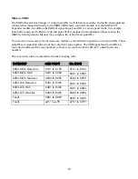
OK 

Early Open 

OL 

Late to Open from Alarm 

OP 

Opening Report 

OQ 

Remote Opening 

OR 

Disarm From Alarm 

OS 

Opening Keyswitch 

OT 

Late To Close 

OU 

Output State – Trouble 

OV 

Output State – Restore 

OZ 

Point Opening 


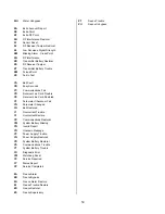
PA 

Panic Alarm 

PB 

Panic Bypass 

PH 

Panic Alarm Restore 

PJ 

Panic Trouble Restore 

PR 

Panic Restoral 

PS 

Panic Supervisory 

PT 

Panic Trouble 

PU 

Panic Unbypass 


QA 

Emergency Alarm 

QB 

Emergency Bypass 

QH 

Emergency Alarm Restore 

QJ 

Emergency Trouble Restore 

QR 

Emergency Restoral 

QS 

Emergency Supervisory 

QT 

Emergency Trouble 

QU 

Emergency Unbypass 


RA 

Remote Programmer Call Failed 

RB 

Remote Program Begin 

RC 

Relay Close 

RD 

Remote Program Denied 

RN 

Remote Reset 

RO 

Relay Open 

RP 

Automatic Test 

RR 

Power Up 

RS 

Remote Program Success 

RT 

Data Lost 

RU 

Remote Program Fail 

RX 

Manual Test 

RY 

Test Off Normal 


SA 

Sprinkler Alarm 

SB 

Sprinkler Bypass 

SC 

Change of State 

SH 

Sprinkler Alarm Restore 

SJ 

Sprinkler Trouble Restore 

SR 

Sprinkler Restoral 

SS 

Sprinkler Supervisory 

ST 

Sprinkler Trouble 

SU 

Sprinkler Unbypass 


TA 

Tamper Alarm 

TB 

Tamper Bypass 

TC 

All Points Tested 

TE 

Test End 

TH 

Tamper Alarm Restore 

TJ 

Tamper Trouble Restore 

TP 

Walk Test Point 

TR 

Tamper Restoral 

TS 

Test Start 

TT 

Tamper Trouble 

TU 

Tamper Unbypass 

TW 

Area Watch Start 

TX 

Test Report 

TZ 

Area Watch End 


UA 

Untyped Zone Alarm 

UB 

Untyped Zone Bypass 

UG 

Unverified Event – Untyped 

UH 

Untyped Alarm Restore 

UJ 

Untyped Trouble Restore 

UR 

Untyped Zone Restoral 

US 

Untyped Zone Supervisory 

UT 

Untyped Zone Trouble 

UU 

Untyped Zone Unbypass 

UX 

Undefined 

UY 

Untyped Missing Trouble 

UZ 

Untyped Missing Alarm 


VI 

Printer Paper In 

VO 

Printer Paper Out 

VR 

Printer Restore 

VT 

Printer Trouble 

VX 

Printer Test 

VY 

Printer Online 

VZ 

Printer Offline 


WA 

Water Alarm 

WB 

Water Bypass 

WH 

Water Alarm Restore 

WJ 

Water Trouble Restore 

WR 

Water Restoral 

WS 

Water Supervisory 

WT 

Water Trouble 


Summary of Contents for SDACT

Page 1: ...User s Manual for Keltron SDACT and FDACT Fire Dialers Keltron Corporation 101A First Avenue Waltham MA 02451 Voice 781 894 8710 fax 781 899 9652 SFDACT DOC Rev 2 2 11 1 06 626 2104 P N 92MSDACT...

Page 2: ......

Page 3: ...allation Overview 19 Selecting a Location 19 Wall Mounting 19 Field Wiring Power Supply Connections 20 Field Wiring Supervised Hardwired Alarm Zones 22 Field Wiring Power Monitor Zones 23 Field Wiring...

Page 4: ......

Page 5: ...is operating properly and can successfully report an alarm the fire dialer must be tested immediately after installation and periodically thereafter according NFPA 72 Chapter 10 and the enclosed test...

Page 6: ......

Page 7: ...nals such as fire trouble water flow or supervisory can be reliably transmitted These signals are typically provided by the general alarm general trouble etc relay contact outputs of the FACP In addit...

Page 8: ...m and general trouble contact outputs The alarm output indicates serial port derived events that are pending transmission and input zone activations The trouble output indicates telephone line faults...

Page 9: ...ble and alarm with 24 hour trouble resound Line seizure is provided for use with shared phone lines as allowed by the local authority having jurisdiction A manual test button is included A silence pus...

Page 10: ...or products approved after July 23 2001 the REN for this product is part of the product identifier that has the format US AAAEQ TXXXX The digits represented by are the REN without a decimal point e g...

Page 11: ...alarm zone inputs is required for UL Listed installations remotely monitoring FACP S via the Public Switched Telephone Network To indicate the supplementary and or redundant nature of the serial data...

Page 12: ...CTBX Listed Signaling Device Enclosure 4 10K EOL resistors P N 64K3355 10K 2 Modular patch cords P N 63RJ4507 1 Programming utility CD P N SDSFDPrgmr 1 Printed user manual P N 92MSDACT For SDACT only...

Page 13: ...with conduit knockouts Hinged front access door with key lock all keyed alike Size 14 H x 17 W x 4 D Weight 12 lbs Environmental specifications Relative humidity 0 to 93 non condensing Operating tempe...

Page 14: ...zone status 4 red 4 yellow 2 Serial port status 1 red 1 yellow 4 Telephone line status 2 red 2 yellow 2 Relay output status red Audible 92 DB pulsed for alarm steady for trouble User pushbuttons 4 re...

Page 15: ...larm relay energizes and the alarm contact active LED illuminates The audible device sounds the pulsed alarm signal The corresponding event code See appendix A is transferred to the SIA transmitter se...

Page 16: ...eration If User Jumper J8 is installed then an off normal status change on the AC failure zone 5 will illuminate the power fault LED but the trouble relay local audible and the AC Power Failure transm...

Page 17: ...ne line fault is detected The Telco fault LED for that line illuminates The common trouble relay energizes and the trouble contact active LED illuminates The audible device sounds the steady trouble s...

Page 18: ...le in 24 hours if the trouble condition is still present Configuration Trouble The Keltron S FDACT stores user programmable settings in non volatile EEPROM memory The content of this memory is checked...

Page 19: ...ow battery zone 6 or no missing battery zone 7 power monitor zone inputs If all of the power monitor zones are normal the power fault LED goes out If no other monitored conditions require the common t...

Page 20: ...transmitter where is 1 for the primary telephone number and 2 for the secondary telephone number see dialing operation Daily Test Operation If the Keltron S FDACT is configured for 24 hour daily test...

Page 21: ...ion DACR i e the S FDACT will pause sufficient time to receive a dial tone but does not require a dial tone to start dialing The S FDACT always dials using dual tone multi frequency DTMF tones Please...

Page 22: ...nnect the FACP and connect the serial port to his PC or laptop While in programming mode the red and yellow serial port LEDS will alternately light once a second as an indication that programming mode...

Page 23: ...ort SDACT only J4 should be set appropriately for the specific FACP being monitored See Serial Port Installation notes J5 J6 and J7 set the normal condition of the power monitor zones 5 6 and 7 respec...

Page 24: ...18...

Page 25: ...ecting a Location The Keltron S FDACT may be installed in any environment which would be comfortable for a human being Typically the S FDACT will be installed in the same room as the FACP which it is...

Page 26: ...must include the S FDACT load current in the FACP s battery calculations Connect the 24 VDC supply making sure to observe the correct polarity Connect the positive lead to terminal 15 Connect the retu...

Page 27: ...the PSU SPSU terminal TB1 3 or TB1 4 Using the Edwards System Technology EST2 Aux Power Output The EST2 s 24 VDC non resettable auxiliary power circuit is compatible with the S FDACT Connect S FDACT t...

Page 28: ...llel at the monitored device Four EOLRs are provided for this purpose Keltron part number 64K3355 10K Connections to the alarm zones are as shown above Input zones are sampled every 62mS Changes must...

Page 29: ...zones 5 6 and 7 may be used as external power source monitor input circuits Each zone is independently configurable for either normally open or normally closed dry contact programmable activation The...

Page 30: ...lephone Line Connection The Keltron SDACT and FDACT are alarm dialing equipment and must be able to seize the telephone line and place a call in an emergency situation They must be able to do this eve...

Page 31: ...07 Plug one end of the modular cord into the S FDACT RJ 45 jack Plug the other end into the RJ31X jack For reference proper wiring of the RJ31X jack is shown in the figure below The S FDACT is electri...

Page 32: ...S or CTS set by J1 and J2 8 CTS or RTS set by J1 and J2 9 No connection IMPORTANT The FACP serial data connections provide supplementary alarm information only Use of the hardwired alarm zone inputs i...

Page 33: ...ions connect the S FDACT Trouble Relay contacts to the 7100 panel by means of an FCI AMM 2 Monitor Module or equivalent The AMM 2 is an addressable dry contact monitoring module compatible with the 71...

Page 34: ...rd electrical box adjacent to the S FDACT enclosure Connect the S FDACT Trouble Relay Normally Open contact terminal 22 to the AMM 2 violet wire Connect the S FDACT Trouble Relay Common contact termin...

Page 35: ...CT when transmitting EST2 events Local Trouble Annunciation For on premises annunciation of S FDACT trouble conditions connect the S FDACT Trouble Relay contacts to the EST2 panel by means of a Signat...

Page 36: ...hen transmitting MIR2 events Local Trouble Annunciation For on premises annunciation of S FDACT trouble conditions connect the S FDACT Trouble Relay contacts to the MIR2 panel by means of a Signature...

Page 37: ...31 SDACT Field Wiring Connection Diagram...

Page 38: ...32...

Page 39: ...o delay 1 3 hours The S FDACT programmer is a Windows PC application SFDPrgmr exe to configure an SDACT or FDACT for use The S FDACT programmer is compatible with Windows XP Windows 2000 Windows NT an...

Page 40: ...Trouble Restore Power Monitor Tab As shown in the figure below the power monitor tab is used to set the event codes for the three unsupervised power monitor zones The AC power monitor input zone 5 has...

Page 41: ...manual test Set Telephone Numbers These boxes are used to set the primary and secondary telephone numbers that S FDACT will dial when reporting Both must be set before uploading the configuration to t...

Page 42: ...Set Options Telephone Lines Used The default setting is for S FDACT to use and supervise both of its telephone line connections If a second telephone line is not available checking the line 1 only opt...

Page 43: ...sync time mode and any values you entered for the date and time will be overwritten by current values from your PC s clock Set Date and Set Time Use these boxes to manually set the date and time to be...

Page 44: ...en a previously saved S FDACT configuration file Save Saves the current configuration settings to the previously opened file If no file was opened previously it displays a standard Windows file save a...

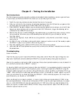
Page 45: ...8 After the S FDACT has reported the zone restore to normal the S FDACT should return to the idle all normal state Troubleshooting In case of trouble Check for the proper power input with sufficient v...

Page 46: ...n Corporation 101A First Avenue Waltham Massachusetts 02451 Telephone 781 894 8710 Toll Free 800 966 6123 FAX 781 899 9652 Email info keltroncorp com GENERAL Telephone 781 894 8710 Email info keltronc...

Page 47: ...improper installation or application The warranty does not extend to products that have been repaired or altered outside our factory without our written approval Except as provided above Keltron Corpo...

Page 48: ...42...

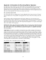
Page 49: ...only and do not network more than 15 panels Otherwise ambiguous SIA Zone numbers will result Also please verify that the central station receiver and central station automation computer are compatibl...

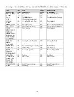
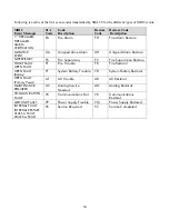
Page 50: ...FV Fire Supervision Restoral MLT EVENTS UA Untyped Zone Alarm UH Untyped Alarm Restore SHORT DISCONNECT MISSING WRONG TYPE EXTRA ADDR CONFIG ERR LOOP BREAK FT Fire Trouble FR Fire Restoral TEST FAIL...

Page 51: ...added to the field programmed account numbers For example if the programmed account number is 1000 then events from unit number 1 ALU1 QZU1 EZU1 report on account 1000 Events from unit number 2 will...

Page 52: ...ORMAL FS Fire Supervisory FV Fire Supervision Restoral SHORT CM SHORT DISCONNECT MISSING WRONG TYPE EXTRA ADDR CONFIG ERR TROUBLE LOOP BREAK FT Fire Trouble FR Fire Restoral TEST FAIL DIRTY VERY DIRTY...

Page 53: ...No conversion is necessary for the detectors modules and notification appliance circuit point IDs Those point IDs are transmitted directly as the 4 digit SIA zone number The EST2 panel fault point ID...

Page 54: ...RVISORY FS Fire Supervisory FV Fire Supervision Restore SHORT FAULT OPEN FAULT FT Fire Trouble FR Fire Restoral OPEN FAULT Battery YT System Battery Trouble YR System Battery Restoral OPEN FAULT Prima...

Page 55: ...is necessary for the detectors modules and notification appliance circuit point IDs Those point IDs are transmitted directly as the 4 digit SIA zone number The MIR2 panel fault point IDs are converted...

Page 56: ...RVISORY FS Fire Supervisory FV Fire Supervision Restore SHORT FAULT OPEN FAULT FT Fire Trouble FR Fire Restoral OPEN FAULT Battery YT System Battery Trouble YR System Battery Restoral OPEN FAULT Prima...

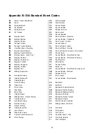
Page 57: ...CW Was Force Armed CX Custom Function Executed CZ Point Closing DA Card Assigned DB Card Deleted DC Access Closed DD Access Denied DE Request to Enter DF Door Forced DG Access Granted DH Door Left Op...

Page 58: ...ld JO Log Overflow JP User On Premises JR Schedule Executed JS Schedule Changed JT Time Changed JV User Code Changed JX User Code Deleted JY User Code Added JZ User Level Set KA Heat Alarm KB Heat Byp...

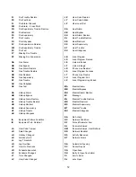
Page 59: ...Alarm SB Sprinkler Bypass SC Change of State SH Sprinkler Alarm Restore SJ Sprinkler Trouble Restore SR Sprinkler Restoral SS Sprinkler Supervisory ST Sprinkler Trouble SU Sprinkler Unbypass TA Tamper...

Page 60: ...Trouble YE Receiver Line Card Restored YF Parameter Checksum Fail YG Parameter Changed YH Bell Restored YI Overcurrent Trouble YJ Overcurrent Restore YK Communications Restoral YM System Battery Missi...

Reviews: