3-15
3. Under
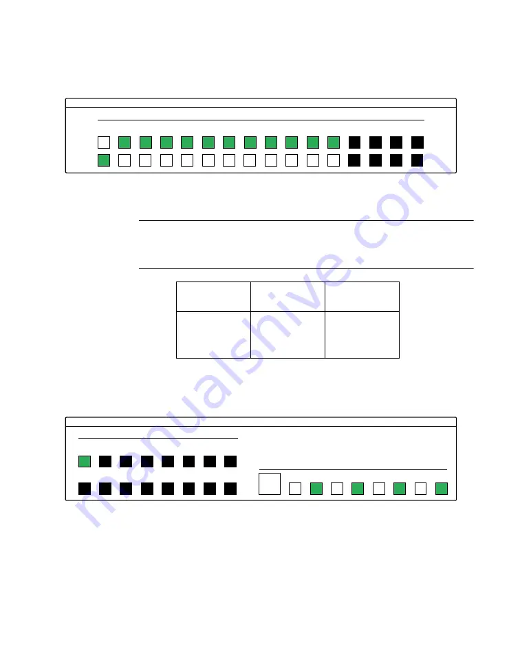
Digital I/O Configuration Panel
, configure channels as
shown in Figure 3-5. (Actual channels available will vary according
to your hardware.)
Figure 3-5. Configuring the digital I/O channels as inputs and outputs
Note:
For clarity when the manual is printed in black and white, the
control colors in Figure 3-5 and subsequent drawings will be shown as
follows:
4. In the
Digital Output Panel
under
Channels
, click on a channel
(here, channel
0
) as shown in Figure 3-6.
Figure 3-6. Configuring channel 0 for output bit pattern A
5. In the
Digital Output Panel
under
Output Bits
, set the bits of the
channel as desired as shown in Figure 3-6. (Click on each bit position
to turn it ON or OFF.)
6. In the
Digital Input Panel
under
Channels
, click on a channel to
select it and display the logical state of its input lines.
Illustration
Color on
Actual Panel
Function
BLACK
DARK GRAY
Invalid
WHITE
LIGHT GRAY
OFF
GRAY
GREEN
ON
KEITHLEY
Digital I/O Configuration Panel
Channel Configuration
Input
Output
0
1
2
3
4
5
6
7
8
9
10
11
12
13
14
15
KEITHLEY
Digital Output Panel
Channels
0
1
2
3
4
5
6
7
7
6
5
4
3
2
1
0
8
9
10
11
12
13
14
15
Output Bits
55


