Verifying the Operation of a Module
57
5
5
5
5
5
5
5
5
5
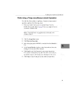
13.
Click
Start
from the Toolbar to start the continuous analog input
operation.
The values acquired from each channel are displayed in a unique color
on the oscilloscope view.
14.
Click
Stop
from the Toolbar to stop the operation.
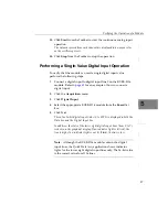
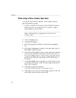
Performing a Single-Value Digital Input Operation
To verify that the module can read a single digital input value,
perform the following steps:
1.
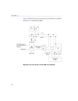
Connect a digital input to digital input line 0 on the KUSB-3116
module. Refer to
for an example of how to connect a
digital input.
2.
Click the
Acquisition
menu.
3.
Click
Digital Input
.
4.
Select the appropriate KUSB-3116 module from the
Board
list
box.
5.
Click
Get
.
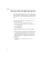
The entire 16-bit digital input value (0 to FFFF) is displayed in both the
Data box and the Digital Input box.
In addition, the state of the lower eight digital input lines (lines 0 to 7)
is shown in the graphical display. If an indicator light is lit (red), the
line is high; if an indicator light is not lit (black), the line is low.
Note:
Although the KUSB-3116 module contains 16 digital
input lines, the Quick Data Acq
application shows indicator
lights for the lower eight digital input lines only. The 16-bit value
is the correct value for all 16 lines.
Summary of Contents for KUSB-3116
Page 10: ...Contents x...
Page 14: ...About this Manual xiv...
Page 15: ...1 1 Overview Hardware Features 2 Supported Software 4 Getting Started Procedure 5...
Page 20: ...Chapter 1 6...
Page 26: ...Chapter 2 12...
Page 64: ...Chapter 4 50...
Page 65: ...51 5 Verifying the Operation of a Module Overview 53 Running the Quick Data Acq Application 54...
Page 75: ...61 A Ground Power and Isolation Connections...
Page 78: ...Appendix A 64...
Page 82: ...Index 68...

