


4
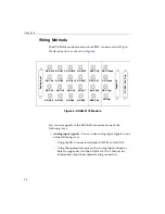
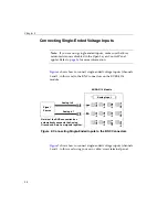
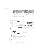
Wiring Signals
27
4
4
4
4
4
4
4
4
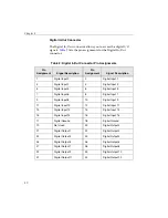
•
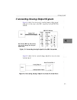
Analog output signals
– You can wire analog output signals in
one of the following ways:
−
Using the BNC connectors labelled DAC Ch0 to DAC Ch3.
−
Using the appropriate pins on the C\T, DAC, Clk, Trig
connector. Refer to Appendix A in the
KUSB-3116 User’s
Manual
for information about the required mating connectors.
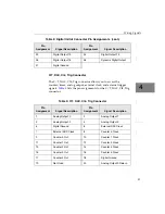
•
Digital I/O signals
– To wire digital I/O signals, you must use
the appropriate pins on the Digital I/O connector. Refer to
Appendix A in the
KUSB-3116 User’s Manual
for information
about the required mating connectors.
•
Counter/timer signals
– To wire counter/timer signals, you must
use the appropriate pins on the C\T, DAC, Clk, Trig connector.
Refer to Appendix A in the
KUSB-3116
User’s Manual
for
information about the required mating connectors.
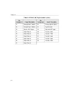
•
External A/D clock or trigger signal
– You can wire external
clock/trigger signals in one of the following ways:
−
Using the BNC connectors labelled AD Clock and AD Trig.
−
Using the appropriate pins on the C\T, DAC, Clk, Trig
connector. Refer to Appendix A in the
KUSB-3116 User’s
Manual
for information about the required mating connectors.
•
External DAC clock or trigger signal
– You can wire external
clock/trigger signals in one of the following ways:
−
Using the BNC connectors labelled DAC Clock and DAC Trig.
−
Using the appropriate pins on the C\T, DAC, Clk, Trig
connector. Refer to Appendix A in the
KUSB-3116
User’s
Manual
for information about the required mating connectors.
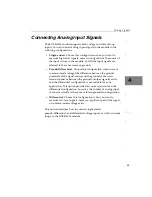
The following sections describe how to wire signals using the BNC
connectors and how to wire signals using the appropriate D-sub
connector.
Summary of Contents for KUSB-3116
Page 10: ...Contents x...
Page 14: ...About this Manual xiv...
Page 15: ...1 1 Overview Hardware Features 2 Supported Software 4 Getting Started Procedure 5...
Page 20: ...Chapter 1 6...
Page 26: ...Chapter 2 12...
Page 64: ...Chapter 4 50...
Page 65: ...51 5 Verifying the Operation of a Module Overview 53 Running the Quick Data Acq Application 54...
Page 75: ...61 A Ground Power and Isolation Connections...
Page 78: ...Appendix A 64...
Page 82: ...Index 68...


