T-GPS User Manual Version 1.2 | 27
4.21
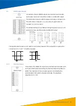
Delay Compensation Output Module
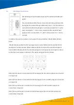
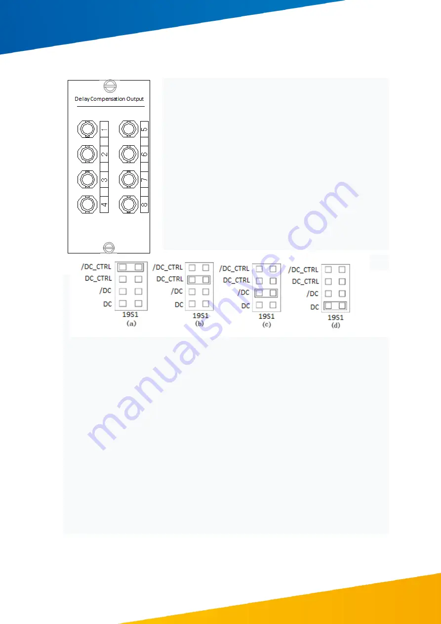
Each delay compensation output modules provides 8 optical
IRIG-B signals.
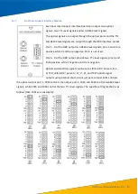
The S2 code jump switch labelled "No Time Delay" on the
printed board is used to set whether the output is
compensated. When the S2 code jump switch is short-
circuited (plug in a short-circuit), the output signal is not
compensated.
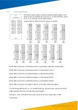
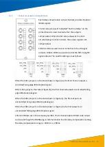
19S1 to 19S4 are used to control the first to fourth signal
outputs; 19S6 to 19S9 are used to control the fifth to eighth
signal outputs. The specific settings are as follows:
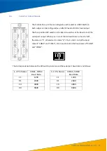
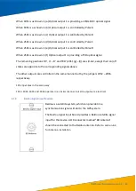
When the 19S1 jumper is in the state shown in Figure (a), the first channel outputs a
controlled rising edge IRIG-B optical signal.
When 19S1 jumps to the state of figure (b), the first channel outputs a controlled falling
edge IRIG-B optical signal.
When the 19S1 jumper is in the state shown in Figure (c), the first output is an
uncontrolled rising edge IRIG-B optical signal.
When the 19S1 jumper is in the state shown in Figure (d), the first output is an
uncontrolled falling edge IRIG-B optical signal.
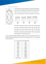
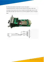
19S2 to 19S8 are set in the same way as 20S1. The 8-channel optical IRIG-B code output
can be set through the 19XS8 plug-in communication line for delay compensation setting.
The delay compensation range is -400ms to + 200ms.

