Digital mode operation:
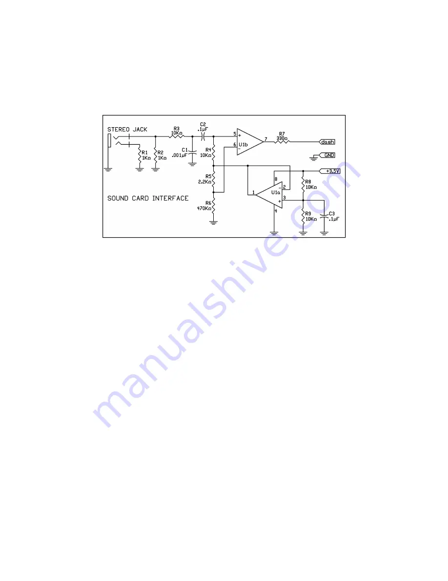
Before any digital mode can be used, you must build the digital interface shown below. The op amp must be a rail to rail
output type which can operate at 3.5 volts, such as a ST microdevices TS-952. At the moment, kits are not available for this
interface, but maybe at some time. If built with SMT parts, it can be made small enough to fit inside the Altoids tin along with
the ATS-3B board, or it can be built into it's own separate tin, which is likely the best way to do it. Two “AAA” batteries would
power it for a long time, provided it has an on/off switch!
R1 and R2 are required when the interface is used in conjunction with a Pocket PC. Without these loads, the Pocket PC will
turn the internal microphone off. R3 and C1 form a low pass filter, which cleans up the audio from the sound card, which has
a lot of high frequency noise on it. R8 and R9 form a voltage divider to provide a bias voltage of ½ the supply and is buffered
by U1a to form a low impedance voltage source. R5 and R6 form another voltage divider so that the non-inverting (+) input to
U1b is slightly more positive than the inverting input when there is no signal input. This ensures the output of U1b will be in a
high state when not being used and will not interfere with normal paddle operation if it left connected to the dash input all the
time. Like wise, R7 isolates the output of the U1b op amp from the dash input so it will not interfere with normal paddle
operation. A sine wave audio input applied to the stereo jack will be converted to a square wave on the output of U1b. The
input must be of sufficient amplitude to ensure switching occurs at or near the zero crossings so that a 50% duty cycle
square wave output is obtained.
Entering ATS3-B into digital mode operation:
Click and hold the MENU switch until the letter “D” is sounded by the side tone and appears on the 7 segment display (as a
lower case “d”).
Once in digital mode, only the quick Menu functions of frequency and battery voltage are available. The Frequency tune
switches work as normal. A direct frequency entry is available in the Pocketdigi application. A click and hold of the Menu
switch exits digital mode.
Running Pocketdigi:
The Pocketdigi program is located in a folder on the CD. There are two zipped folders. The one which the names ends with
_X86 is for use with Windows operating systems in either a Desktop or Laptop PC. The one which name ends with _ARM
has versions for use a PDA using Windows CE or Window mobile. The file named “Pocketdigi” is used in a PDA. The one
named htx2000 is for hand held PC's, which are larger than a PDA. Unzip the files in the folder to one on your PC. A good
place to put it would be in “My Documents” so it can be easily found. Pocketdigi runs as an executable file. It does not install
as a program file. Simply click on the file name to run it. If the Windows firewall is active, you will be asked if you really want
to run it. Of course you do, click yes.
A comprehensive operations manual for Pocketdigi has yet to be written. Vojtech in waiting for someone to volunteer. Most of
the functions are self evident and intuitive, working in much the same way as programs you are probably familiar with.
The screen is divided into three sections. The top is the waterfall. The operating frequency is set by tapping or clicking on the
waterfall above the scale showing the frequency, or on a signal trail. The center section is the received text screen and the
32


