


22
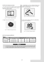
Fig. 8-12 Requirements for power cord connection
Fig. 8-13 Wiring of unit communication and the
wired controller communication
8.4.7 Requirements for power cord connection
8.4.8 Function of terminals
16
L1 L2 L3 N
L1
L2 L3
N
L1 L2 L3 N
L1
L2 L3
N
XT2
L1/L2/L3
HEAT1 HEAT2 COM COMP-STATE
PUMP
HEAT1
PUMP
COM
N
XT1
COMP-STATE
HEAT2
Correct
Wrong
NOTE
Please use the round-type terminal with correct specifications to
connect the power cord.
Uint communication The wired controller
communication
As shown in the figure below, the uint communication signal wire
is connected to the terminal block XT2 at 5(X), 6(Y) and 7(E),
and the wired controller signal wire is connected at 8(X), 9(Y)
and 10(E) inside the electric control box. For specific wiring, see
chapter 8.4.13.
When the water pump and auxiliary heater are added externally,
a 3-phase contactor must be used for control. The model of
contactor is subject to the power of water pump and heater power.
The contactor coil is controlled by the main control board.
See the figure below for coil wiring. For specific wiring, see
chapter 8.4.14.
The user can connect an ac light to monitor the state of
compressor. When the compressor is operating, the light will be
powered on.
The wiring of water pump and pipeline auxiliary heater and ac light
of the state of compressor is as follows.
Coil of 3
phase AC
contactor
Coil of 3
phase AC
contactor
220-240V~
50Hz
N
220-240V~
50Hz
N
CN26(Main board)
CN33(Main board) CN25(Main board)
Max voltage: 240VAC
Max current: 5A
Max voltage: 240VAC
Max current: 5A
L1/L2/L3
Coil of 3
phase AC
contactor
Coil of 3
phase AC
contactor
Fig. 8-14 Wiring of water pump and pipeline auxiliary heater
and
ac light of the state of compressor(only for KEM-30
DRS4.1 and KEM-60 DRS4.1)
Fig. 8-15 Wiring of water pump and pipeline auxiliary heater and
ac light of the state of compressor (only for KEM-90 DRS5)
8.4.9 Wiring of “ON/OFF” weak electric port
The remote function of “ON/OFF” must be set by DIP switch. The
remote function of “ON/OFF” is effective when S5-3 is chosen
ON, at the same time, the wired controller is out of control.
Corresponding parallel connect the “ON/OFF” port of the main
unit’s electric control box, then, connect the “ON/OFF” signal
(provide by user) to the “ON/OFF” port of main unit as follows.
The remote function of “ON/OFF” must be DIP switch set.
Wiring method: Shorting the terminal block XT2 at 15 and 24
inside the electric control box to enable the remote function of
“ON/OFF” .
Summary of Contents for KEM-90 DRS5
Page 52: ......