


16
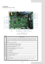
8.3.2 MAIN PCB
1) Label descriptions are given in Table 8-3
26
1
28
2
3
4
5
6
7
8
9
10
11
12
13
15
16
18
19
20
21
22
24
25
27
29
30
31
32
33
34
35
36
37
38
41
40
42
43
44
45
46 47
17
23
14
39
Fig. 8-8 Main PCB of KEM-90 DRS5
Table 8-3
NO.
Detail information
1
CN30: Input of three-phase four-wire power supply (fault code E1) Input of transformer, 220-240V AC current. (only
valid for the main unit) Three phases A, B and C of power supply should exist 120° among them. If the conditions
are not met, fault of phase sequence or phase lack may occur, and fault code will be displayed. When the power
supply returns to normal condition, fault is removed. Attention: phase lace and phase dislocation of power supply are
detected only in the early period after the power supply is connected, and they are not detected while the unit is in
operation.
2
CN12: Quick return oil solenoid valve
3
CN80: Injection solenoid valve of compressor system B
4
CN47: Injection solenoid valve of compressor system A
5
CN5: Water side heat exchanger heaters connection
6
CN40: Multi-function solenoid valve
7
CN13: Electric of water side heat exchanger heaters connection
8
CN41: Liquid bypass solenoid valve
9
CN42: Crankcase heater
10 CN6: Four-way valve
11 CN43: Crankcase heater
12 CN4/CN11: Electric heater of water flow switch
13 CN27: Three-way valve (hot-water valve)
14 CN86: SV2, Spray cooling valve
15 CN25: Pump
1) After receiving start-up instruction, the pump will be started up instantly, and will maintain start-up state always in
the process of operation.
2) In case of refrigerating or heating shutdown, the pump will be shut down 2 minutes after all modules stop
operating.
3) In case of shutdown under the pump mode, the pump can be directly shut down.
Summary of Contents for KEM-90 DRS5
Page 52: ......


